Физика/7. Оптика
S.N. Kurilkina, N.I.Mukhurov V.N. Belyi
B.I. Stepanov Institute of Physics of NAS of Belarus,
Minsk, 220072, Belarus
e-mail: s.kurilkina@
ifanbel.bas-net.by
Evanescent Bessel tip for near-
field microscopy
One of
the most important classes of propagating-invariant fields is the Bessel light
beams (BLBs) [1]. Last decade evanescent BLBs are of great interest for many
researchers. These beams are generated in less denser medium under the
condition of total internal reflection, exponentially decay with propagation
but retain their original transversal shape. At that, its diameter can be
reduced to a value of submicron order [2-4]. This determines the possibility of
using evanescent Bessel beams in optical microscopy. But the investigated before
single evanescent BLB possesses an essential disadvantage, namely, together
with bright central maximum, it contains a number of annular lateral maxima.
This leads to a significant energy loss in the central part of the light beam
and decreases the efficiency of application of evanescent BLBs in optical
microscopy. In the present paper the effective method permitting to eliminate
this disadvantage is proposed. The possibility of the use of a superposition of
evanescent Bessel light beams as virtual tip is considered.
In the
paper [4] the problem is solved of transmission and reflection of vector Bessel
beams at the boundary of two dielectrics under the conditions of total internal
reflection. The relations for the electric and magnetic vectors of the evanescent
Bessel beam generated inside the less dense medium are obtained. Using Ref.[4],
the equations can be found for the longitudinal and transversal energy flow
densities formed by the superposition of N
circularly polarized Bessel light beams with equal amplitudes and phases
incident onto the boundary of dielectrics under the conditions of the total
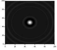
internal reflection. On the base of this it is established that for the
superposition of two evanescent Bessel beams with equal and different
topological charges an essential suppression of lateral maxima of the radial
distribution of the longitudinal energy flow density and an increase of the
energy concentration in near-axis area take place (Fig.1). At that, the numerical
simulation confirms that the half-width of the central maximum at a level of
0.5 for the generated superposition of non-vortex evanescent BLBs (first annual
maximum for the superposition of evanescent vortex BLBs) is determined by the
beam having the maximal half-cone angle. Inclusion of BLB with a less half-cone
angle into the superposition causes the transformation of the peripheral area
of the generated evanescent field, i.e. the suppression and shift of lateral
maxima in the transversal distribution of Sz
component of the Poynting vector. A
remarkable property of a superposition of evanescent BLBs is keeping the size
of the central maximum at moving off the media interface (Fig.1).
|
||||||
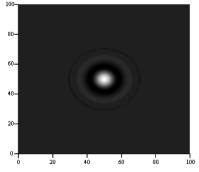
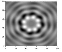
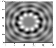
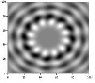
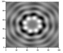
We
established that the evanescent field, generated by the superposition of two circularly-polarized oppositely charged Bessel beams, is characterized by bright first annular maximum and the
azimuthal modulation of longitudinal energy flow in transversal distribution. Owing to it, the energy flow pattern is separated into
substructures similar to single beams with the sub-wavelength transverse size
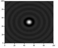
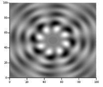
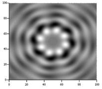
(Fig.2). The numerical simulation confirms that the central near-axis part of mentioned
above substructures are rather stable at moving off from the interface (Fig.3).
|
a |
b |
c |
||
|
Fig. 2. 2D- distribution of the longitudinal projection of the energy
flow density inside air at the distance z=λ/3 μm from the boundary with glass. Incident field is a superposition of
two right circularly polarized BLBs having l=1.06 μm
and following half-cone angles: |
||||
|
a |
b |
c |
||
|
Fig. 3. 2D- distribution of the longitudinal projection of the energy
flow density inside air at the distance |
||||
Thus, using the superposition of two oppositely
charged evanescent Bessel beams one can form near the interface the array of
diffraction-free sub-wavelength light “needles”. This light field can be used
as a virtual Bessel tip. Its principle scheme is proposed
(Fig. 4).
|
|
|
|
Fig.1
8. Scheme of virtual Bessel tip. |
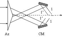
Fig.
2. Scheme of obtaining one of two conical beams. Ax is refractive axicon, CM
is conical mirror, 1 and 1’ are extreme rays of the formed conical beam. |
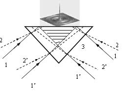
The lateral surface of conical lens 3 is illuminated
by two conical beams 1 and 2 with extreme rays 1 and 1', 2 and 2',
respectively, under the conditions of total internal reflection. Each of the
conical beams is obtained from a circularly polarized collimated Gaussian beam,
using a scheme in Fig.5 [5]. In the
shaded region a superposition of two oppositely charged Bessel beams with large
half-cone angles is formed. If the tested surface is placed at the distance ![]() from the base of the
conical lens 3, the evanescent field of the virtual Bessel tip penetrates into
the surface. Thus, the superposition of evanescent BLBs can be used for testing
the surfaces of various specimens with sub-wave resolution.
from the base of the
conical lens 3, the evanescent field of the virtual Bessel tip penetrates into
the surface. Thus, the superposition of evanescent BLBs can be used for testing
the surfaces of various specimens with sub-wave resolution.
References
[1] J. Durnin, J.Opt. Soc.Am.B, 4, 651, 987.
[2] S. Rushin,
A. Leizer J. Opt. Soc. Am., A15,1139,1998.
[3]
Xi Jiefeng, Li Qing, Wang Jia, Proc. SPIE, 5635, 42,
2005.
[4] S.
N. Kurilkina, V. N. Belyi, N. S. Kazak, Opt.
Comm., 283, 3860, 2010.
[5] V. N. Belyi et al, Opt. Engineering, 50, 059001, 2011.