Технические науки/12. Автоматизированные системы управления на производстве
Cand.Tech.Sci. Belkin E.A.
Orel State Technical University, Russia
Microrelief geometric
simulation and technical application
Abstract
A
theory for the three dimensional (3D) geometrical model definition of surface
layer microrelief on the basis of a modular geometric principle is developed. A
device design for the active control of a microrelief formation process the
operation principle of which is based on the concept of dynamic holography is also
developed. A microrelief formation technique by specified geometrics is
developed.
1. Theory
One of the
reasons affecting considerably the information completeness of a surface
microrelief analytical description is the application of iteration and
statistical methods in the ground of which there is no a concept of surface
curvature in the local area of the specified point – in the vertex of modulus –
of an osculating paraboloid which is estimated by Riemann – Christopher’s
tensor.
Thus,
the statistical description method of abrasive surfaces with the aid of Markov
chain theory allows building only a two dimensional (2D) model including time
steps of cutting along an idealized line towards cutting. It does not allow
taking into account a cutting edge shape in the direction perpendicular to the
vector of a cutting speed and a cutting edge position with respect to
successive cutting edges that is essential at the explanation of material
removal process.
Thus
and so, the development of mathematical modeling methods allowing the
replenishment of information shortage in a surface microrelief description
occupies a significant place in the shaping theory.
To the
main reason which does not allow building a 3D geometrical model strict enough
and adequate to a real microrelief one refers the application of the parameter totality
of roughness Ra, Rz, Rmax and others in one
dimensional (1D) microrelief models, and parameters ωn, ς, γ0, φ1,
θ1, Θ1 in 2D models.
So far there
are no sufficiently complete and well substantiated 3D geometrical models of
microrelief in the mathematical models of a forming and machined surface. In
such a way, for structuring a 3D geometric model of microrelief one should use
new scientific approaches.
A
modular- geometrical method for a surface microrelief geometric simulation is
developed [1].
The
theoretical justification of a modular-geometrical method for a microrelief
geometric simulation is given. The classification of surfaces with a complex
form from the standpoint of geometry cannot have a scientific justification.
There are no common signs in the structure of surfaces. A complex form surface
is structured on the basis of a modular principle, a structuring method is
defined by the problems of a shaping theory. A modular-geometrical method which
is used for the solution of these problems consists in the approximation of the
local area of a surface with an osculating paraboloid. Riemann – Christoffel’s
tensor is a geometric description for the estimate of a local area curvature.
The analytical assignment of an osculating paraboloid as a geometric image of
the second order of contact with the given local area of a surface is defined
from Tailor series expansion. Tailor series also defines geometric images of a
higher order of contact: cuboloid, quadroloid and so forth. A surface curvature
is estimated in the point of contact through the angle of vector rotation
shifted across itself through a closed loop enclosing the point of contact and
appertaining to its local area, on the osculating surface: on paraboloid,
cuboloid and so forth. The angle of rotation on the surface under consideration
depends on vector coordinates:
![]()
![]()
![]()
where Γχρσ
are the affine connectedness coefficients of the second sort,
indices
ν, μ, τ, ω…= 1, 2;
d1xν,d2xμ - coordinate vector differentials.
This
vector is equal to the difference of two vectors obtained as a result of the
parallel displacement of the vector νχ from the vertex of an infinitesimal
parallelogram into an opposite vertex along its sides compiling various parts
of a closed loop. It follows that the expressions in square brackets are
tensors. Thus,
![]() -
-
Riemann-Christoffel’s
tensor, a considerable component of which is R1212, gives the angle
of vector rotation at the parallel displacement through a closed loop on an
osculating paraboloid limiting the local area of its vertex. The accuracy order
in the definition of covariant differential characterizing changes in vector
coordinates does not allow computing a quadroloid curvature. The geometrical
structure of cuboloid is not studied. In technical applications one should
confine oneself to the approximation of a local area by an osculating paraboloid,
as it is possible to postulate in the following way: a surface curvature in the
point of contact is equal to the curvature of an osculating paraboloid.
The
discrete-defined surface of a work piece in a general case can be approximated
through a module set having a smooth “lacing” each of which represents an
osculating paraboloid of a certain type.
It is
established that a modular approach used for the description of the geometry of
framed discrete-defined surfaces at the work piece abrasion may be accepted as
a basis for surface microrelief structuring.
At the
formation of a simulator describing a surface microrelief one uses a modular
principle for structuring a surface with a complex shape and with the solution
of problems of uneven “lacing” of separate modules.
On
account of the complexity of actually current phenomena the consideration of surface
microrelief formation in a work piece is carried out for an ideal model with
the following assumptions: environment does not affect a 3D geometrical model
of surface microrelief, one can neglect chemical, thermal and dynamic
interactions of a tool and a work piece.
There
is obtained an analytical presentation for an osculating paraboloid through principle
surface curvatures. From equations for the total and mean surface curvature of
an osculating paraboloid:
![]()
![]()
where:
K is Gauss or total surface curvature,
H is the mean surface curvature,
k1, k2 are the principle surface
curvatures,
g11, g12, g22 are the components
of a metric tensor,
R1221 is the essential component of
Riemann-Christoffel’s tensor (curvature tensor).
From
Gauss equation:
R1221
= B11B22,
For the
point of contact of the surface under consideration and of an osculating
paraboloid in the approximation:
g11g22 – g212 = 1;
g11
=g22 = 1;
where a
given point has coordinates X = 0, Y = 0.
The
analytical presentation for the osculating paraboloid:
Z
= ½(k1X2 + k2Y2).
The representation
obtained for the osculating paraboloid through the principle surface curvatures,
is a significant result on the basis of which there was carried out a numerical
computation for the modular geometrical model of surface microrelief.
The
system of criteria is established for the quantitative assessment of
microrelief topography: k1, k2 – the principle surface
curvatures, Rz – the microasperity height. The hypothesis
substantiated theoretically with respect to the information exhaustiveness of a
microrelief topography criterion system is advanced.
The
microrelief geometrical model is a body of modules having uneven “lacing” of
osculating paraboloids. Each osculating paraboloid can be presented as one of
four types pointed out in Tab.1, each type of an osculating paraboloid has a
corresponding orientation with respect to Z-axis
in XYZ- local coordinate system.
Table 1. Types of an
osculating paraboloid
|
Surface type |
Name |
Equation
presented |
Surface kind |
В11 |
В22 |
|
I |
Elliptic paraboloid |
|
|
|
|
|
II |
Hyperbolic
Paraboloid |
|
|
|
|
|
III |
Parabolic cylinder |
|
|
|
0 |
|
IV |
Plane |
|
|
0 |
0 |


where ![]() B11,
B22 – the coefficients of the second quadratic form.
B11,
B22 – the coefficients of the second quadratic form.
At the
microrelief surface approximation on experimental data the model accuracy
testing consisted in the estimate of the maximum error δz max at the surface conjugation meant for two
adjacent design points. The value δz
max was defined as a ratio of a maximum jump on Z-axis at the conjugation
of two neighbouring paraboloids to the interval of value changes in experimental
data on Z-axis: Zij max – Zij min . The performed
computations have shown that a surface presentation accuracy depends on the
number of design points falling at the interval of a peak or a trough of
microrelief.
There
is defined a problem for the module factor computation (Tab. 2) of surface
microrelief, in a general case: a surface is decomposed through a chosen pitch
on Z-axis of Cartesian coordinate system by planes parallel to XY-plane and one-parameter family of
surfaces. A subinterval of a family of surfaces is set with respect to a family
parameter. The nodes of microrelief and the families of parallel planes and
surfaces are defined. A module -
surface local area – as a part of the surface of an osculating
paraboloid is rebuilt through five points. The problem solution for a module
factor computation in a particular case for the flat of a part [2] consists in
the following:
Table 2. The module
type definition of the three-dimensional geometrical model (TGM) of microrelief
|
№ |
TGM module type |
Factor sign |
|
1. |
k1X2+k2Y2≥-2Z; |
k1>0;
k2>0; |
|
2. |
k1X2+k2Y2≤-2Z; |
k1<0;
k2<0; |
|
3. |
k1X2+k2Y2≤
2Z; |
k1>0;
k2<0; (k1<0, k2 >0); |
|
4. |
k2Y2≥-2Z |
k1=0;
k2>0; (k1=0, k2<0); |
|
5. |
Z≤0; |
k1=0;
k2=0. |
In the
global system of Cartesian rectangular coordinate system there is set a point
field definable with values n on X-axis and values m on Y-axis.
For each point (xi,yj),
![]() ; there is known a value zij (Fig. 1, 2).
; there is known a value zij (Fig. 1, 2).
A subinterval on x-axis is Δx= (xn-x1)/n. A
subinterval on y-axis is Δy= (ym-y1)/m.
In the
node – (xi+l; yj; zk+1) on the basic area Lx x Ly,
where
1≤i≤nx +1,
1≤ j≤ ny + 1, 1≤ k ≤ (1 + nx)(1 + ny);
![]()
![]()
one defines radii
of curvature Rl1,
Rl2 through
three points in the sections xi+1;
yj; through the nodes of microrelief real
profiles (Fig. 3, 4)
On the basis of
Meunsnier theorem the normal curvatures are calculated in the sections xi+1; yj;:
![]()
![]()
where φ1 and φ2 are the angles between
the principle normal of paraboloid and circular arc normals in the sections xi+1; yj.
Supposing
that a normal curvature in one of the sections is equal to the principle
curvature k1 = kln, through Dupin indicatrix one defines
the principle curvature k2 in the section perpendicular to the
section chosen (Fig. 5, 6).
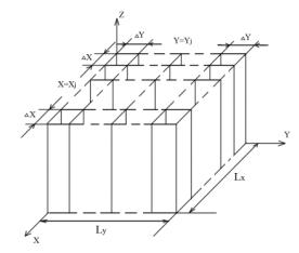
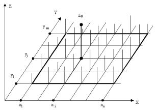
Fig. 1. The
model of microrelief decomposition Fig.
2 . Basic data for the computation
by interperpendecular planes of microrelief
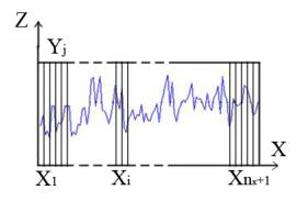
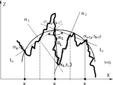
Fig. 3.
Microrelief decomposition in Fig.
4. The scheme to the computation
the plane y
= yi of
the curvature radius in the section
of
y = yi
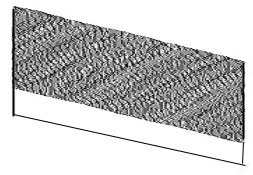
Fig. 5. The
XYZ – coordinate system Fig. 6. The modular
geometrical model
in the
point of contact of
surface microrelief 30x6 mcm of a sample
after
flat grinding:(scanning pitch 0.001mcm)
Through
the values k1 and k2 the type of module for a geometrical
model in Cartesian local rectangular coordinate system with the beginning in
the node –(xi+1;
yj) is defined. The
procedures for the numerical computation are developed for the microrelief of
surfaces (flat, circular cylindrical, framed discrete-defined and solids of
irregular form) [3].
2. Inspection tools for control of microrelief
formation process
Modern
inspection tools are designed in such a way that recorders register the values
of parameters from the outline maps of an object. The outline maps are defined
either with low accuracy, or in the course of a rather long period of time. It
is impossible to carry out control of an out-of-the-way object – abrasive
grains moving in work piece material.
There
is one method among the ways for the enhancement of inspection tool capabilities
and the use of information obtained with their assistance for the creation of
three dimensional models, the application of devices investigating an object
holographic display.
The
control principle of tools under consideration is based on the latest researches
of the processes of obtaining an object holographic display in optical and
X-ray (roentgen) bands. The devices in this line allow studying manufacturing
processes not in a plane projection, but in space.
3. Roentgenoprofilograph of active control
The
problem, for the solution of which is used the device offered, consists in the
provision of possibility to carry out control of a microgeometry formation in a
surface layer of a work piece in the course of abrasion and to research the
mechanism of processes accompanying a microrelief formation: chip removal,
abrasive grain spalling and extraction of abrasive grains from the set of
tools, grain microoscillation appearance in the tool set, changes in porous
structure of a tool set, microchip formation, a plastic shift and strengthening
material to be machined with single grain and grain aggregate and so forth.
It is
achieved by that in a roentgenoprofilograph of active control [4] having X-ray
emitter, a crystal resonator for obtaining monochromatic X-ray emission,
focusing crystal systems –collimators, the principle of operation of one of
them is based on eight-beam diffraction, crystal mirrors for the separation and
change of X-ray emission propagation direction, recording environment – crystal
– analyzer for obtaining wave interference, the increase of a three dimensional
interference image is carried out with the aid of a reflecting microscope at
the recording of a holographic display of the object under research, and for
measuring one uses a three dimensional matrix compiled of electron-optical
image intensifiers.
4. Means for microrelief formation
The
procedure for the prediction of new ways of machining is based on the
theoretical researches of a three dimensional geometrical model of a work piece
surface and consists in that a binary correspondence of a forming surface is
established on the basis of the developed allocation for a work piece surface.
Under this correspondence the prediction of new ways of shaping is carried out.
The
work piece surface is represented as a superposition of a three dimensional
geometrical model with module smooth “lacing” which gives the idea of geometry
in whole and a model with module uneven “lacing” which contains the information
of forming surface microrelief .
Types
of machining are defined.
The
first type: ways allowing reproducing forming surface geometry theoretically
correct. In their basis there is a modification of the contact mode of a tool
and a part blank. The way of grinding the blade wing of a gas turbine with the
aid of profilecomposite tools belongs to the first type. [5]
The
second type: ways permitting the representation of work piece surface
microrelief in accordance with given geometrical data. Changes in the procedure
of machining allowance removal are in their basis. The grinding way with the
use of an elbore tool with a metallic fiber set belongs to the second type. [6]
The
third type: ways allowing reproducing the geometry of work piece surface and
its microrelief theoretically correct and in accordance with the given
geometrical data. Tool microgeometry changes in the course of a work piece
machining are in their basis. The way of gas turbine blade wing grinding with a flexible bundle in a magnetic field belongs
to the third type. [7]
For the
realization of the predictable way of microrelief formation allowing producing
its microgeometry according to the given geometrical data the optional
equipment – counterpart (prototype) of a cyclotron – an elementary particle
accelerator is required.
Abrasive
particles existing in a magnetic field are used as a tool. The analytical
assignment of a part surface: a gas turbine blade wing is used for the
computation of the general homohelical path of abrasive particle motion. To the
charged abrasive particles controlled by a magnetic field pertaining to a blade
wing is imparted a motion by a general homohelical path in accordance with the
type of blade, changes of a helical path of abrasive particles and the
substitution of an abrasive particle fraction.
5. Blade wing grinding method for gas turbine by
flexible tool set in magnetic field
The
problems, which the invention is aimed at, consist in combining in one
production cycle the main abrasion operations of a blade wing in a gas turbine
beginning from roughing and up to finishing in one technological system, in
widening the type spectrum of work blades, shaping accuracy increase in
macrogeometry of a blade wing and at the control on the given data: an abrasion
depth, a temperature field and a curvature tensor and so forth, surface layer
microshaping.
The
problems put by should be solved by the offered method of grinding through
which in a resonance accelerator – cyclotron to the charged abrasive particles controlled
by a magnetic field one imparts, relative to a part, a motion along a general
homohelical path on the basis of conditions securing favourable changes in a
general homohelical shaping surface in accordance with a blade type, changes in
the kind of an abrasive particle helical path in accordance with the given
shaping surface, and a possibility of the fraction substitution of abrasive
grains.
In this
connection, before surface machining (entrance and exit edges, back, tray) one
describes gas turbine blades in an analytical way on the basis of the modular
geometrical model of a surface with a complex shape, the obtained analytical
assignment of a blade wing is used for the computation of a general homohelical
path of abrasive particles.
Conclusions:
1.
The method for the definition of microrelief topography is developed
which allows building a three dimensional geometrical model of microrelief on
the basis of experimental data.
2.
A possibility for the substantiation of the prediction of tool
development for passive and active nondestructive control allowing carrying out
estimations on the basis of three dimensional geometrical models is given.
3.
The prognostics in the
development of devices for passive and active nondestructive control of a
microrelief formation process is carried out, the control principle of which is
based on the latest researches of processes in obtaining a holographic image of
objects in optical and roentgen bands.
4.
The substantiation for the possibility of forecasting new machining
methods allowing microrelief forming by given geometric data is presented.
5.
The recommendations for forecasting the method for a microrelief
formation allowing the representation of its microgeometry by given geometric
data, abrasion methods of a blade wing for a gas turbine in a flexible bundle
in a magnetic field are given.
References
[1] Y.S. Stepanov, E.A. Belkin, G.V. Barsukov,
”Simulation of abrasive tool microrelief and part surface”, Monograph, M.:,
Publishing House “Mashinostroyenie-1”, 2004, pp. 215, Patent RF № 2229970,
Method for manufacturing elbore abrasive tool in metal fiber bundle/ Y.S.
Stepanov, E.A. Belkin, G.V. Barsukov, Patent application 29.07.2002, published 10.06.2004, Bulletin №
16.
[2] Patent RF № 2187070, “Method for part and
abrasive tool surface microgeometry definition” / Y.S. Stepanov, E.A. Belkin,
G.V. Barsukov, Patent application 27.02.2001, published 10.08.2002, Bulletin №
22.
[3] Certificate № 2008612886, Software
“CAD-Grinding”, E.A. Belkin, Patent application 25.12.2007, registered 11.06.2008.
[4] Patent FR № 280204, “Roentgenprofilograph
for active control”/ E.A. Belkin, Patent application 24.10.2005, published
12.02.2007, Bulletin № 22
[5] Patent RF № 2217290, “Method for blade wing
grinding by profilecomposite tools for gas turbine” / Y.S. Stepanov, E.A.
Belkin, G.V. Barsukov, Patent application 26.03.2002, published 27.11.2003, Bulletin
№ 33
[6] Patent RF № 2229970, “Method for
manufacturing elbore abrasive tool in metal fiber bundle”, / Y.S. Stepanov,
E.A. Belkin, G.V. Barsukov, Patent application 29.07.2002, published
10.06.2004, Bulletin № 16
[7] Patent RF № 2266188, “Method for blade wing
grinding of gas turbine by tools with flexible bundle in magnetic field”, /
E.A. Belkin, Patent application 22.03.2004, published 20.12.2005, Bulletin №
35.