Lebedev V.A.
RADIATION
CONFIGURATION FACTORS
FOR A FLAT
CYLINDRICAL SPIRAL
Institute of Thermophysics SB
RAS, Novosibirsk, Russia
Используя
свойство осесимметричных излучающих систем, исследуется аналитическая форма
представления угловых коэффициентов самооблучения внутренней поверхности
ленточной спирали и оценивается доля лучистой энергии, «запертой» в полости
спирального нагревателя.
Using
the properties of axial-symmetric emitting systems, the analytical formula was
obtained for a coefficient of self-irradiation of the inner surface of a flat
infinite cylindrical spiral.
Due to
an expanding scope of engineering problems dealing with radiation heat
transfer, the necessity of calculation of the radiation configuration factors
(RCFs) has emerged in last years. These coefficients Fi - j define the fraction of ray energy emitted from
the surface i reaching the surface j. Since 1985 only two handbooks are
available ([1] and its following Eds, and [2]) that give information about RCFs
for different systems at the level acceptable for engineering applications,
although much information has been obtained in this field by numerous
researchers for recent years. Before these handbooks were published, data on
analytical or numerical form of RCF for a specific configuration of emitting
system has been presented only in the monograph [3] (and its oth. Eds), but in
amount not sufficient for practical applications. Besides, in these books and
the articles from periodic technical magazines, calculations of RCFs (in analytical
or graphical forms) for some kinds of emitting systems were not presented yet.
For example, among those unexplored objects there are spiral and helical
emitting systems. Indeed, the last category is presented in a single paper
devoted to Moebius band [4].
This
paper is an attempt to obtain the RCFs for a spiral emitting system (in particularly,
for a flat cylindrical spiral), which has not been presented in publication
yet. Here we use the approach proposed in papers [5,6,7] which are recommended
for use by authors of [1] and [3].
Fig.1
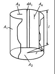 Let us consider a
RCF Fd 1-2 from an elementary
strip dA1 along the whole
generatrix of cylinder A1
to the base of cylinder A2
(Fig. 1). We can write an equation which is true for mutual surfaces H1-2 and H2-1 of the emitting
system the cylinder’s base – its wall: H2-1 + H2-3 = A2F2-1 + A2F2-3 = A2 (taking into account the
closure ratio F2-1 + F2-3 = 1), or, since we
have H2-1 + H1-2 =
Let us consider a
RCF Fd 1-2 from an elementary
strip dA1 along the whole
generatrix of cylinder A1
to the base of cylinder A2
(Fig. 1). We can write an equation which is true for mutual surfaces H1-2 and H2-1 of the emitting
system the cylinder’s base – its wall: H2-1 + H2-3 = A2F2-1 + A2F2-3 = A2 (taking into account the
closure ratio F2-1 + F2-3 = 1), or, since we
have H2-1 + H1-2 = ![]() , we obtain
, we obtain
 .
(1)
.
(1)
Since H2-3 = F2-3A2, then (1) takes the form  , after that we have
 . (2)
. (2)
Substituting into
(2) the value ![]() , we can write this equation in the form
, we can write this equation in the form ![]() , or
, or ![]() , so we can obtain the value of integral RCF from the
cylinder wall towards the base of cylinder:
, so we can obtain the value of integral RCF from the
cylinder wall towards the base of cylinder:
![]() . (3)
. (3)
The
local RCF Fd 1-2 from elementary
strip dA1 on the
generatrix of the cylinder A1 by its definition depends on area A2 and height dA1. Since A2 is constant and the
emitting system has an axial symmetry, we obtain that Fd 1-2 = const (i.e., the
magnitude is independent of the position of the strip dA1 on the cylinder wall), then from (2) we have
![]() . (4)
. (4)
Comparing (3) and
(4), we see that F1-2 = Fd 1-2, i.e., RCFs
towards the base of the cylinder from the wall and from its elementary strip
along its generatrix (of infinite small width) are equal each other. This is a
foundation to believe that we have the same RCF from the lateral surface
between any two generatrices towards the base of cylinder. This is derived from
the properties of reciprocity and closure for RCFs. Let us prove this through
an analysis of a discrete case.
Remember
that the RCF from one end surface towards another one and towards lateral walls
are related through the ratio, which characterizes the property of closure:
F2-1 + F2-3 = 1.
(5)
Splitting the
surface A1 into n equal parts An = A1/n (see Fig. 1) between the generatrices
and the bases of the cylinder, we present equation (5) in the form:
 ,
,
or
![]() , (6)
, (6)
which is obvious
due to axial symmetry of the emitting system. Using the reciprocity
relationships ![]() , we obtain from (6) RCFs for radiation from An to A2:
, we obtain from (6) RCFs for radiation from An to A2:
![]() ,
,
or
![]() . (7)
. (7)
The RCF Fn-2 is independent of
the splitting number and transforms into the local RCF for the specific
configuration of the system at n ® ¥.
From
(3), (4) and (7) we see that F1-2 = Fd 1-2 = Fn-2 = inv, meaning
that RCFs are equal by their magnitudes, they are independent of the width of
emitting strip, but depend only on radius r
of disk A2 and length l of cylinder A1, since only these geometrical parameters affect A1, A2 and F2-3 [1 - 3]:
![]() .
.
To obtain an RCF
for a spiral, we can use the RCF F2-n from the cylinder face A2 to the strip of a final width An, which is parallel to the cylinder axis, on the wall.
This RCF can be obtained from (6) or (7)
using the reciprocity ratio:
![]() . (8)
. (8)
Fig.2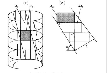
Let us divide the inner lateral surface of the cylinder into k cylindrical rings of equal height.
Then the strip An will be
divided by vertical into equal k
parts with equal areas Ak
(Fig. 2, а). Then the following
condition will be satisfied:
![]()
![]() , where
, where ![]() are not equal RCFs
from the cylinder’s end A2
to equal surfaces Ak,
which are equal parts of co-axial rings being at different distances from A2. For that, the magnitudes
of F2-n and F2-k would not change if
every ring segment Ak
would take an arbitrarily position on its “own” ring. This is derived from the
symmetry of the considered system.
are not equal RCFs
from the cylinder’s end A2
to equal surfaces Ak,
which are equal parts of co-axial rings being at different distances from A2. For that, the magnitudes
of F2-n and F2-k would not change if
every ring segment Ak
would take an arbitrarily position on its “own” ring. This is derived from the
symmetry of the considered system.
Since
the position of sections Ak
does not affect on the values F2-n and Fn-2 , i.e., every section can be arranged arbitrary
within its “own” ring, these sections can be arranged as a stepwise spiral (Fig.
2b); for this spiral we can take RCFs
Fn-2 at ![]() and
and  . As one can see from (7) and (8), the values of RCF are
independent on the horizontal splitting, unlike it was for vertical splitting.
Then, at k®¥,
Ak ®
dAk we obtain the RCFs Fn-2
and F2-n
in analytical form of presentation like (3), (4), (7), and (8) for emitting
system in the form of a cylindrical spiral, placed between disks A2 and A3, with a radius of r,
equal to the spiral radius. The total area of the inner emitting surface of the
spiral is
. As one can see from (7) and (8), the values of RCF are
independent on the horizontal splitting, unlike it was for vertical splitting.
Then, at k®¥,
Ak ®
dAk we obtain the RCFs Fn-2
and F2-n
in analytical form of presentation like (3), (4), (7), and (8) for emitting
system in the form of a cylindrical spiral, placed between disks A2 and A3, with a radius of r,
equal to the spiral radius. The total area of the inner emitting surface of the
spiral is  . For this splitting, the height of the spiral element dAk becomes infinitely small,
and its width, measured in the plane (parallel to planes A2 and A3)
remains constant, fixed by the distance between two vertical generatrices ¾ the boundaries of
the strip An, whose
elements compose the spiral.
. For this splitting, the height of the spiral element dAk becomes infinitely small,
and its width, measured in the plane (parallel to planes A2 and A3)
remains constant, fixed by the distance between two vertical generatrices ¾ the boundaries of
the strip An, whose
elements compose the spiral.
Let us
consider the self-irradiation of the inner surface of the spiral with radius r with the length l (the height of the forming cylinder A1). If the RCF Fn-1 defines the portion
of emission emitted from the strip An
(i.e., as it was shown above, from the inner surface of a spiral) to the
lateral surface of cylinder A1,
then, accounting the closure rule Fn-1 + Fn-2 + Fn-3 = 1 and Fn-2 = Fn-3, and from (7) we
obtain:
![]() . (9)
. (9)
Since for practical
calculation the case of a “long” spiral is most interesting, we can consider
the situation at l >> r. Then (from the conditions of system’s
closure and symmetry) the self-irradiated surface An of a cylindrical flat spiral composes a shear of the
lateral inner surface of the cylinder A1;
the latter was used for construction of emitting and self-irradiating system in
the following proportion: An /A1 = hc /H,
where H is the spiral pitch, hc is the width of emitting
strip of the spiral (measured in direction parallel to system’s symmetry axis: hc = h /cos a, here h is the width of emitting strip, a is the inclination angle of
the spiral turn (see Fig. 2, b). Then
from this reasoning and from (9) we obtain that Fn-n / Fn-1 = An / A1 = hc /H and RCF for self-irradiation of a
spiral is as follows:
![]() . (10)
. (10)
For a case of a
“long spiral” we have r/l ® 0. Then one can see from the
geometry of the system that (A2/A1) ® 0 and F2-3 ® 0; so RCF for
self-irradiation of a flat cylindrical spiral (the band was transformed into
the spiral) takes the following analytical form:
![]() , (11)
, (11)
which is extremely
simple and useful for practical calculations.
References:
1. J.R. Howell, A
Catalog of Radiation Configuration Factors. McGrow-Hill Book Co., N. Y.,
San Francisco, Toronto, 1983, 1985 & www.engr.ukyedu/rtl/Catalog/
2. N.A. Rubtsov, V.A. Lebedev, Geometric Invariants of Emission,
Novosibirsk, 1989.
3. R. Siegal, J.R. Howell, Thermal Radiation Heat
Transfer.
(4th edition,Teylors & Francis), N. Y., 2001.
4. A.L. Stasenko, The self-radiation
of Moebius band with a fixed shape, Izvestiya AN SSSR, ser. Energetika i
Transport, n. 4, pp.104 - 107,1967.
5. V.A. Lebedev, Invariance of
radiation shape factor for certain radiating systems, Izvestiya SO AN SSSR,
ser. Techn. Nauk, n. 13, iss. 3, pp. 73 - 77, 1979.
6. V.A. Lebedev, About relationships
between radiation configuration factors for cylindrical emitting systems, Soviet Journal of Applied Physics, Vol. 11,
n. 3, pp. 12 - 16, 1988.
7. V.A. Lebedev, Geometricheskie invarianty izlucheniya spiralevidnyh nagrevateley, Teplofizika i
Aeromekhanika, Vol. 10, n. 1, pp. 101 - 108, 2003.