Technical Sciences / 5.Energetics
Rozum T.I., Polichshuk V.I.
Tomsk Polytechnic University
Protection
of synchronous machine rotor windings from damage
Currently,
generators with a capacity of 500-800 MW and above are used in large
quantities, respectively, which requires timely troubleshooting, in turn, to
turn short circuit in field winding due to the high operating temperature.
First, a short circuit at two points belongs to a very dangerous damage to the
field winding of synchronous machines [1]. Closures on the ground at one point
winding for synchronous machines are not dangerous, as the current value in the
scheme of arrangement is equal to zero. Lack of power in some corners is the
asymmetry of the magnetic rotor, which is accompanied by vibration. Vibration
can quickly lead to the destruction of the bearings and the shaft journal. A simple way to protect the excitation
winding from turn-to-turn short circuit [2] of two magnetic sensors is suggested.
At a turn-to-turn short circuit current in the closed rotor coils of
synchronous machine is missed, and a magneto motive force (MMF) of damaged
poles and its magnetic field decreases in proportion to the number of turns
shutting![]() . Thereby, the protection device operation is based on
a comparison of a magnetic field of synchronous machine coil-end leakage at two
poles. To do this, it is necessary to use a pair of magnetic field sensors, MFS1
and MFS2, which are displaced along the air gap at a distance multiple of pole pitch
. Thereby, the protection device operation is based on
a comparison of a magnetic field of synchronous machine coil-end leakage at two
poles. To do this, it is necessary to use a pair of magnetic field sensors, MFS1
and MFS2, which are displaced along the air gap at a distance multiple of pole pitch
![]() . The example of those magnetic sensors disposition for the synchronous
machine with
. The example of those magnetic sensors disposition for the synchronous
machine with ![]() at
at ![]() is shown in the Fig. 1. The pairs of
excitation winding poles
in this figure are marked as
is shown in the Fig. 1. The pairs of
excitation winding poles
in this figure are marked as ![]() ,
, ![]() ,
,![]() .
.
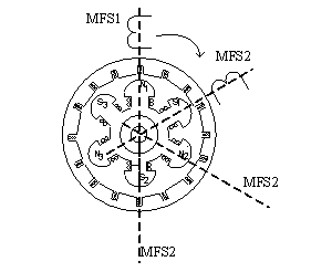
Fig. 1 Versions
of two magnetic sensors position for synchronous machine at![]()
The
protection is realized by the block scheme in Fig. 2 , where the magnetic
sensors 1 and 2 are fastened on the end shield; the magnetic sensor is attached
to the comparing element so that ![]() and
and ![]() in the inputs of comparing element for
any n could be in the opposite phase,
CB- comparison block, B - band-pass filter, TE - threshold element; LS –
load-break switch.
in the inputs of comparing element for
any n could be in the opposite phase,
CB- comparison block, B - band-pass filter, TE - threshold element; LS –
load-break switch.
The
information sign selection is done
by the graph-analytical analysis. In the magnetic sensor EMF ![]() is induced by stationary stator
winding with a current frequency of
is induced by stationary stator
winding with a current frequency of ![]() Hz, and
Hz, and ![]() is induced by excitation winding rotating with an angular velocity
is induced by excitation winding rotating with an angular velocity ![]() at a constant current
at a constant current ![]() . EMF
. EMF ![]() in the output of the filter F will be equal in value and its sum will be
equal to zero. Therefore, when analyzing, the difference of
in the output of the filter F will be equal in value and its sum will be
equal to zero. Therefore, when analyzing, the difference of ![]() EMF
EMF ![]() cannot be ignored in the future.
At the same time, the value of EMF
cannot be ignored in the future.
At the same time, the value of EMF ![]() was determined by the
magnetizing force of the rotor pole. Therefore,
when the rotor is intact, these EMFs
are equal to each other, and if the rotor is damaged, EMFs are different. The result is that the
sum of the EMF
was determined by the
magnetizing force of the rotor pole. Therefore,
when the rotor is intact, these EMFs
are equal to each other, and if the rotor is damaged, EMFs are different. The result is that the
sum of the EMF ![]() of magnetic sensors 1 and 2 at
the output of BS is determined by the amount of EMF
of magnetic sensors 1 and 2 at
the output of BS is determined by the amount of EMF ![]() from the excitation winding
poles.
from the excitation winding
poles.
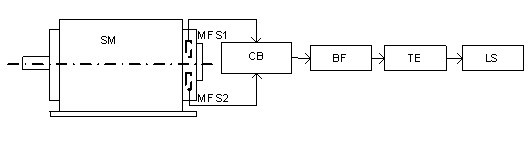
Fig.2 Block
scheme of the device for implementation of the protection of the synchronous
machine rotor with two magnetic sensors
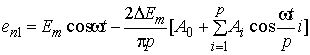
As a result, at the synchronous rotation of the rotor with an intact
winding EMF of the first converter is defined as:
![]() , (1)
, (1)
where ![]() – peak EMF
from magnetizing force of the intact rotor pole;
– peak EMF
from magnetizing force of the intact rotor pole; ![]() - angular
line frequency;
- angular
line frequency; ![]() – time.
– time.
At turn-to-turn
ground short circuit winding of one of the rotor poles, the magnetizing force
decreases, as the current in closed windings is equated to zero. This will lead to a decrease the half-wave
amplitude of EMF ![]() by
by ![]() induced in magnetic sensor 1 by that
pole. Given the
fact that all the poles of the rotor are transmitted nearby magnetic sensor 1
during the one complete circuit of the rotor
induced in magnetic sensor 1 by that
pole. Given the
fact that all the poles of the rotor are transmitted nearby magnetic sensor 1
during the one complete circuit of the rotor ![]()
![]() relation
relation ![]() in the
circuit of some part of turns in one of the poles of the synchronous machine at
in the
circuit of some part of turns in one of the poles of the synchronous machine at
![]() . This relation expanded into Fourier's series and converted into account
the filter F effect and at the number of analogous poles
. This relation expanded into Fourier's series and converted into account
the filter F effect and at the number of analogous poles ![]() can be written as
can be written as
 , (2)
, (2)
where ![]() ;
; ![]() – a number
of turns in the pole winding.
– a number
of turns in the pole winding.
EMF ![]() at the output
of BS obtained by numerical expansion
in Fourier’s series for the different location of magnetic sensors [3] is as
follows:
at the output
of BS obtained by numerical expansion
in Fourier’s series for the different location of magnetic sensors [3] is as
follows:
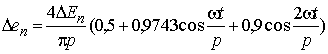 , (3)
, (3)
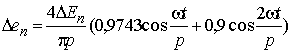 , (4)
, (4)
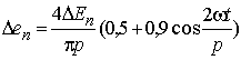 . (5)
. (5)
The analysis of the expressions obtained and Fig. 3 shows that to
construct a rotor protection with ![]() from turn-to-turn ground short circuit, you can use all the components
from turn-to-turn ground short circuit, you can use all the components ![]() that are listed in (3), (4) and (5). However, the use of the second
component of the series
that are listed in (3), (4) and (5). However, the use of the second
component of the series ![]() is more preferable, since it is present at any location of measuring
transducers. The choice depends on the availability of the presence of the
device protection signals and its power and in the fault-free excitation
winding.
is more preferable, since it is present at any location of measuring
transducers. The choice depends on the availability of the presence of the
device protection signals and its power and in the fault-free excitation
winding.
At closing of excitation winding to the ground at two points, any amount
of turns can be closed and the data signal will be stronger.
In the proposed method of protection a signal of turn-to-turn short
circuit in excitation winding can be as a harmonic ![]() as well a constant component of
EMF sum at the output of magnetic sensor.
as well a constant component of
EMF sum at the output of magnetic sensor.
References
1. Федосеев А.М. Релейная защита электрических систем. – М.: Энергия. –
1976.– 559с.
2.
Новожилов А.Н., Горюнов В.И., Полищук В.И., Воликова М.П., Новожилов Т.А.
Способ защиты обмотки ротора синхронного генератора от витковых замыканий на
двух индукционных преобразователях// Электричество. – 2010.- №8. – С.65–67.
3. Бессонов Л.А. Теоретические основы электротехники.
– М.: Высшая школа, 1973. – 752 с.