Cand.Tech.Sci. Kobersi I.S., Cand.Tech.Sci. Ignatyev V.V.,
Shapovalov
I.A., Odei Ph.
Southern
Federal University, Russia
Partial
report on work on dc to ac inverter
A direct current (dc) to
alternating current (ac) inverter is a device used for changing a dc supply to
an ac supply. Direct current is an electrical supply whose polarity does not
change with time. Typical examples of dc sources are electrical energy obtained
from batteries, electrical energy from photovoltaic (pv) cells and some
electromechanical Generators (dc generators). Also dc current can be obtained
by passing ac through unidirectional electronic components like the diode.
The energy and power
content of dc is constant since the magnitude of the supply voltage does not
change with time. Alternating current is a source of electrical energy whose
polarity changes with time. An ac supply is generated by letting coils of wire
cut through magnetic field or the coil can be fixed while the magnetic field
changes. This relative movement causes current to be induced in the coils and
is called electromagnetic induction. The induced emf follows Faraday’s law of
electromagnetic induction: an induced electromotive force (emf) is setup
whenever the magnetic field linking that circuit changes; the magnitude of the
induced emf in any circuit is proportional to the rate of change of the magnetic
flux linking the circuit; the direction of the induced emf is given by Lenz’s
law and further expanded by Fleming’s Right – hand rule which are respectively
stated as; the direction of an induced emf is always such that it tends to set
up a current opposing the motion or the change of flux responsible for inducing
that emf.
![]()
Where, E is the induced voltage, B is the flux
density, l the length of coil, v the velocity of the coil and Ө the angle
the coil make with the magnetic field. The right hand rule is a mnemonic for the relationship between the
directions of current flow, motion, and magnetic field in electromagnetic
induction. The hand is held with the thumb, first, and second fingers at right
angles, respectively indicating the directions of motion, field, and electric
current. Since dc is unipolar and ac is bipolar, to change dc to ac it
means that the polarity must be reversed at the rate of 50Hz. One way of doing
this is to setup the circuit of fig. 1.
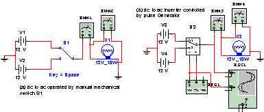
Fig. 1
In fig 1(a) two dc
sources are used and are switched in alternately which gives the load in this
case a lamp the impression of receiving alternating current. For each switching
the voltage across the lamp swing from +12v to -12v which are respectively
equal to V1 and V2. Current 833,236mA Fig. 1(b) the switch is controlled
with a signal from XFG 1 a signal generator. At very low frequency the current through
lamp and voltage across the lamp are observed to fluctuate from -833,236mA to
-833,236mA and 12V to -12V dc. At a frequency of 50Hz the meters see the supply
as ac and the voltage is indicated as 9,019V which is approximately given as:
V![]() ,
,
Where D is the duty
cycle of the square wave. Fig. 2 shows the same circuit with transformer
coupling and a square wave from a signal generator drives the circuit. Fig. 2(a)
was implemented using dual supply and the result is given below.
Load current: XMM 5 = 832,754mA XMM
7 = 2,212A
Load voltage: XMM 6 = 99,753V XMM 8 = 103,832V
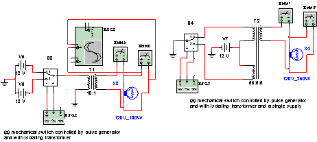
Fig. 2
It is also possible to
carry out this switching of dc to ac with single supply when a centre tapped
transformer is used like in fig. 2(b). The H configuration show in fig. 3
where four switches are necessary to carry out the switching is very much
popular in design of electric machine drive circuit. It is necessary to maintain
the correct sequence of the on/off of the four switches. To use a single source
in fig. 3 and for current to flow through the load, switches sw1 and sw4
are switched «on» or switches sw2 and sw3 are switched «on». It is prohibited
to put on switches sw1 and sw2 at the same time as this will cause short
circuit. Likewise switches sw3 and sw4 cannot be on together.
A B
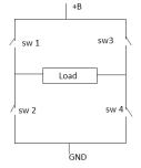
Fig. 3
In the transistorized form
of the above circuit each switch is replaced with the emitter- collector or
source – drain terminals for transistor or MOSFET or IGBT respectively.
Switches sw2 and sw4 form the low end of the switching circuit. They do not
have much problem in their design as normal electronic switching circuits with
components correctly chosen rating will work. The problem of using H type
switching circuit is in the design of the upper switching part. It should be
remembered that during operation points A and B takes the value of the full
potential which means the switching supply should equally be high voltage to be
able to give the necessary switching.
The circuits exhibited
so far are using direct square wave which is not an efficient way of inverting
dc to ac due to high content of unwanted harmonics components. This problem of
harmonic is taken care of by using several other circuit topologies which
include pulse width modulator.
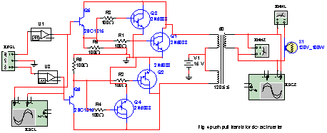
Fig. 4.
Fig. 4 show another
version of a push – pull arrangement utilizing Darlington pare transistor at
the output and at the input two pulse width modulators U1 and U2 to provide the
necessary complementary pulses to drive the two sets of transistor.
The discussion so far
has tried to explain the operation of a dc to ac inverter. The next stage is to
look at the block diagram and come out with a functional diagram with all the
feedback paths included. The real work of the thesis can then be analyzed base
on a functional circuit.
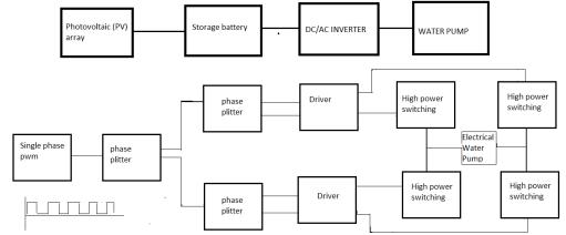
Fig. 5
References
1. «Advanced Electrical
Power Systems Thrust» Office of Naval Research website, www.onr.navy.mil, last
accessed 30 May 2004.
2. Paul Fillmore, «Design,
construction, and testing of a hysteresis controlled dc-ac power converter for
paralleling» Master’s thesis, Naval Postgraduate School, Monterey, California,
2003.