Introduction
Short circuit in the
low-voltage network is a failure state, at which the short-circuit current with
dynamic and thermal influences damages or even destroys parts of distribution
network. The aim of protection devices is to avoid this. .
For cases when the short–circuit is created by electric conductive connection with a neglected impedance the short–circuit current magnitude is sufficient for reaction of upstream protection devices (circuit–breakers, fuses). The calculation methods of short-circuit currents are well known. As a rule the maximum values of short-circuit current is calculated. The other and very unfavourable situation is the case when the impedance in the place of short – circuit is higher and so the protection devices don’t react. It is the case of arc short – circuit, when the current is flowing through the ionised space. In this case the arc impedance cannot be neglected. Just the influence of the arc impedance on the magnitude of short –circuit current is necessary to be solved in this case.
The arc impedance is not constant, it mainly depends on the arc length, arc cooling and on the current flow through the arc. Problems by the determination of arc impedance are caused first of all by voltage gradient on the arc column. In dependence from the conditions, in which the arc burns, the gradient will change in wide boundaries. Typical values of arc voltage gradient are within 10 and 100 V/cm. Important fact is, that arc impedance depends on the current, which is flowing through the arc. There are no theoretical methods for determination of the arc impedance. The calculation of impedance from volt-ampere characteristic of arc is only possible for static arc burning by DC voltage. However this is not our case (arc roots move during the short-circuit, arc column changes its length, parallel arcs can arise and so on). Determination of the impedance by the equation of dynamical arc [Slamecka] is not possible either, because for stabilised arc with round cross section the channel model of arc is valid. As a convenient way for solution of this problem we assume to be a computer simulation and mainly experimental investigation of arc voltage and arc impedance of free burning arc between band conductors.
Origin reasons and consequences of
arcing faults
With arcing faults we meet already more years both in the distributions of self-consumption of power plants and in the industrial distributions of large enterprises (chemical, converting plants). Results achieved show that arcing faults from low – voltage distributions cannot be eliminated. Therefore it is necessary to minimise the consequences of arcing faults and to search the possibilities of arcing faults elimination and the fast current interruption.
Arcing fault origins when insulating condition between the conductors of various potentials decreases down to unused value – the breakdown of surface or air distance arises. Analysis of various cases of service show that reasons can be characterised as follows:
- creation of conductive way based on the insulation degradation,
- additional mechanical, thermal, electrical overload,
- switching overvoltage,
- foreign body in the switchboard (tools, animals),
- human operation (work on the live equipment),
- connection unlocking (screw contact, flexible laminated contact).
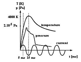
After arc origin in the switchboard approximately after time of 10 ms pressure in the ambient of burning arc achieves its maximum (Fig. 1). After next 5 ms the temperature in the arc ambient achieves maximum value too. From the energy balance point of view 50 % of arc energy shares on the increase pressure, 35 % is removed by radiation and conduction. The energy rest 15 % shares on the erosion of material of current paths (bus–bars, terminals) in the place of arc root.
From erosion point of view it is very important if the arc is in the motion or if it is stationary. In the case of the stationary arc approximately 5–10 grams of conductive material melts in 1 second at the value current of 1000 A [1,2]. For higher currents destruction of current path also for shorter arcing time is very expressive. When the arc is movable the thermal stress is essentially lower and the probability of its spontaneous extinguishing is higher.
In the case of metal–enclosed switchboard the overpressure usually causes the overrun of mechanical strength and the housing destruction follows. Toxic gas mixture and melted particles of material are spread into the ambient. These melted particles can cause resulting fire.
Switchboards are designed so that there are insulating barrier plates between the current-carrying parts and tap lines have additional insulation. There are increased insulating distances so that the arcing fault cannot start contingently and its effect is reduces. But the practice shows that even such arrangements cannot eliminate the arcing fault. The upstream protection elements and devices however under these conditions don’t react because the current value is relatively low and deficient for a function of protection element. Conventional electronic systems for a protection against the arcing faults check in the failure and activate the upstream protection device. The extinguishing and interruption times however can be very long for all. Light-sensitive sensors are used for detection of arcing fault in the switchboard, which react on the flash at origin of arc. For a decreasing time of arcing fault it is possible to use electromagnetic instantaneous short-circuiting device. This device short-circuits the bus bars in the switchboard and changes the arcing fault into a “metal” short-circuit. The consequence is an increase of the current and switch off the feeder switch. This is a principle of operation of the ARCON protection system from MOELLER (Fig. 2) [1, 3].
Fig. 2. The protection
system ARCON.
1 – main busbar system, 2 – current sensor, 3 – feeder switch, 4 – arcing fault,
5 – light sensor, 6 – electronic evaluation unit, 7 – instantaneous short-circuiting device, 8 – threshold sensor
Because the
arcing short-circuit is always accompanied by expressive changes of pressure,
the pressure might be used to initialise the short-current switch integrated in
the switchboard. Of course, the switchboard should be closed hermetically.
Constructional options allowing an arc to extinguish by itself are another
options. This is only possible if the arc is allowed to move freely, to prolong
itself and extinguish eventually. All these options are limited, as the current
can set up in any place of a construction so that the given constructional
option need not be always effective. Let us keep in mind that old switchboards
are still operated, even if not convenient for the present needs and increased
energy consumption. In
Simulation
The calculation programs for computation of short-circuit currents assume conditions giving a maximum current values. These results serve for a specification of short-circuit capability of electrical equipments. For protection against arcing faults it is necessary to calculate minimal values of short-circuit currents. This task is demanding because it is influenced by various factors. It is very complicated to determine the impedance which at origin of arcing fault influences the magnitude of short-circuit current. Using of a simulation program has solved this problem.
Initiation of the arcing fault between leading–in wires is a transient effect, which is possible to solve by calculation or by simulation program. In the case of simulation the result is in a convenient graphic form.
The transient effect is given by the magnitude of network voltage, of network parameters and of initiation instant of the zero value of the voltage (angle α). We are interested first of all one the short-circuit current-time curve (magnitude and time of current flow). For the analyse of the effect we considered the network voltage 42 V line-to-line, assumed short-circuit current 10 kA by power factor cosφ=0.5. Initiation instant of the short-circuit was variable within 0 and 180 electrical degrees. This values influence more or less expressively the evolution of transient effect or do not at all (α=φ). The simulation code solves the basic differential equation
![]()
(1)
The solution has the form
 (2)
(2)
 where
where ![]() is the supply voltage,
Um is the amplitude of
supply voltage, ω is the angular frequency, α is the initiation instant of the short-circuit current with respect to the foregoing zero
value of the supply voltage,
is the supply voltage,
Um is the amplitude of
supply voltage, ω is the angular frequency, α is the initiation instant of the short-circuit current with respect to the foregoing zero
value of the supply voltage, ![]() is the phase shift, R, L are the resistance and inductivity of the
network, Z is the
impedance, t1 is the time of arc voltage maximum,
is the phase shift, R, L are the resistance and inductivity of the
network, Z is the
impedance, t1 is the time of arc voltage maximum, ![]() is the arc voltage
(constant value). Equation (2) describes the time behaviour of current during
the arcing fault interruption of the test circuit supplied from a generator.
is the arc voltage
(constant value). Equation (2) describes the time behaviour of current during
the arcing fault interruption of the test circuit supplied from a generator.
 In the position of a
short-circuit in the first case a non-resistive connection was considered, then
the voltage drop is zero and in the circuit flowed assumed short-circuit
current. In the following case creation of arc voltage with values 100, 200 and
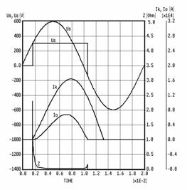
300 V was considered. Such course we can see on Fig. 3 solved by simulation
program, where Ik is assumed short-circuit current, Io is the
limited current, Ua is arc voltage (300 V), Us is supply
voltage and Z is arc impedance. From the courses it is seen the influence of arc
voltage on the short-circuit current limitation. The amplitude of short-circuit
current was decreased from 16,6 kA down to 6,6 kA and time of current flow was
shortened from 11,5 ms to 8,5 ms.
In the position of a
short-circuit in the first case a non-resistive connection was considered, then
the voltage drop is zero and in the circuit flowed assumed short-circuit
current. In the following case creation of arc voltage with values 100, 200 and
300 V was considered. Such course we can see on Fig. 3 solved by simulation
program, where Ik is assumed short-circuit current, Io is the
limited current, Ua is arc voltage (300 V), Us is supply
voltage and Z is arc impedance. From the courses it is seen the influence of arc
voltage on the short-circuit current limitation. The amplitude of short-circuit
current was decreased from 16,6 kA down to 6,6 kA and time of current flow was
shortened from 11,5 ms to 8,5 ms.
The higher is the arc voltage the more expressive is the current limiting [5]. Arc impedance was calculated too, which is given by ratio of arc voltage and short-circuit current. From its time curve we see on Fig. 2, that at the beginning and at the end of the curve it reaches high values, because the value of short-circuit current is low. In the area of maximal current the arc impedance is in wide boundaries almost constant and its value is in the range of 10-2 Ω. Simulation shows an expressive influence of arc voltage on the short-circuit current curve. By the high values of arc voltage the amplitude of short-circuit current and the time of current flow dropped essentially.
Experimental investigation of arcing
faults
Results from the experimental investigation of arcing faults practically don’t exist, there is no well-known arc behaviour neither the grade of destruction in dependence on the current magnitude and arcing time. The experiments have been made in the cooperation with Nuclear Power Plant Research Institute. First experiment was only made at one half-wave of short – circuit current – in the circuit with condenser battery as a source of short-circuit current. Diagram of test circuit is seen on the Fig. 4. Circuit parameters (R, L, C) determine time behaviour of current, current magnitude is given with charging voltage magnitude of condenser battery. In our case the magnitude of assumed current achieved 15 kA at length of half–wave 10 ms near to the sinusoidal course.


Arc behaviour at passage of more current half–waves was investigated in the test circuit with short-circuit generator, diagram is seen on Fig. 5. For a voltage 420 V line to line the current reached magnitude of 10 kA at time of current flow up to 0,2 s. After this time the current was interrupted by means of back-up circuit breaker.
Arcing faults were investigated in the low – voltage switchboard with dimensions 800 x 700 x 2245 mm, connecting bars 10 x 60 and tap line bars 8 x 30 mm from aluminium and painted with colour. Tap line bars were in two places reinforced with insulating rungs. In the tap line bars a circuit breaker J2UX was placed. Diagrammatic plan of switchboard field is seen on Fig. 6. Because the place of arc origin can influence the course of phenomena during short-circuit (arc motion, arc voltage magnitude, arcing time), these determined ten places on the switchboards, in which during experiments the arc was initiated. The arc was initialised by melting of copper wire with diameter of 0,65 mm.
 During the experiments the
voltage course on the current path and short-circuit current course was
recorded with the digital oscilloscope TEKTRONIX 2430 A. Arc voltage was
interesting because from its time course we could judge the arc behaviour
during the short-circuit.
During the experiments the
voltage course on the current path and short-circuit current course was
recorded with the digital oscilloscope TEKTRONIX 2430 A. Arc voltage was
interesting because from its time course we could judge the arc behaviour
during the short-circuit.
![]() Already the experiments in the test circuit with condenser battery
and one current half-wave were accompanied with intensive phenomena. Wire
melting and arc origin displayed explosion and strong light rays. When the arc
had a possibility, it moved very quickly. Speeds exceeded value 100 m/s.
If the arc met an obstacle
Already the experiments in the test circuit with condenser battery
and one current half-wave were accompanied with intensive phenomena. Wire
melting and arc origin displayed explosion and strong light rays. When the arc
had a possibility, it moved very quickly. Speeds exceeded value 100 m/s.
If the arc met an obstacle
on the way – insulating rungs, housing of circuit breaker, then the arc stopped. In the place of arc roots the busbars were melted and melted aluminium spurted to all directions. The phenomena intensity was proportional to the current magnitude and time of its duration. Significant results from these experiments are, that during the arc burning the current amplitudes achieved only 6 – 7,5 kA. In comparison with the amplitude of assumed current (15 kA) it has gone to an expressive current limiting. Typical oscillogrames are on Fig. 7. On the upper course is the voltage drop on the busbars (measuring scale 100 V/d) and on the lower course is current course flowing through the arc (2 kA/d). Time scale in all cases is 2 ms/d.
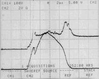
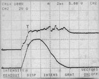
Fig. 7. Time course of arc voltage and current in the circuit with condenser battery.
Experiments in the test circuit with short-circuit generator and with assumed currents up to 10 kA and time duration up to 0,2 s give a similar character of phenomena. Two typical phenomena are frequent. If the arc has any possibility quickly to move and increase its length (bump of arc column on the busbars end), an expressive current occurs and the arc extinguishes after two up to four current half-waves. This process influences the place of arc origin. Incidental phenomena were similar as at the experiments in the test circuit with condenser battery. The phenomena are more interesting and more intensive in the case when the arc is stabilised on the insulated parts.
The arc had an endeavour to burn on the surface of insulator (sometimes extinguished but again initiated and burnt until the current interruption by means of back-up circuit breaker). Incidental phenomena were very intensive and were connected with arcing time. Dangerous was a geyser of melted aluminium.
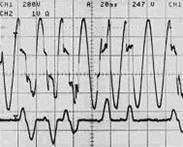
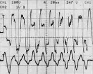
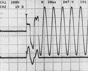
Typical courses of electrical variables are on Fig. 8. On the upper course is voltage drop on the busbars (measuring scale 200 V/d) and on the lower course is current course flowing through arc (5 kA/d). Time scale in all cases is 20 ms/d [4]. On the Fig. 8a is the typical time behaviour the both variables for a case of spontaneous and fast arc extinguishing. The arc roots move on the busbars and increase the arc length. Arc voltage achieves value up to 300 V.
a) b) c)
Fig. 8. Time course of arc voltage and short circuit current in the circuit with generator.
The arc had an endeavour to burn on the surface of insulator (sometimes extinguished but again initiated and burnt until the current interruption by means of back-up circuit breaker). Incidental phenomena were very intensive and were connected with arcing time. Dangerous was a geyser of melted aluminium.
Typical courses of electrical variables are on Fig. 8. On the upper course is voltage drop on the busbars (measuring scale 200 V/d) and on the lower course is current course flowing through arc (5 kA/d). Time scale in all cases is 20 ms/d [4]. On the Fig. 8a is the typical time behaviour the both variables for a case of spontaneous and fast arc extinguishing. The arc roots move on the busbars and increase the arc length. Arc voltage achieves value up to 300 V.
Time behaviours on the Fig. 8b are characteristic for a case, when the arc is stabilised on the insulating parts. Arcing time is long and current interruption sets in by means of back-up circuit breaker. Immovable arc melts material of busbars, current course is expressively deformed by arc voltage. In the Fig. 8c arc origin is given by surface break down of insulation at voltage value 400 V after time 20 ms. The current course has a currentless intervals with length up to 40 ms.
There are various reasons leading to the origin of arcing faults. The thermal damages due to the arcing faults are essential higher as mechanical and thermal stress of current path, with flowing short-circuit current. Arcing faults can cause bad injuries of humans and destruction of switching station equipment. Production failure and power failure in the energy distribution network are another disadvantages.
How will the old
distribution networks work under these conditions? It is highly recommended to
perform proper tests to judge the working ability of the switchboard.
Insulating state of the switchboard is tested by a voltage surge, a thermal
test by a thermographic method. Also, the real duty
current of a switchboard is measured and the network supply voltage is
analysed.
If needed and where needed, a melting power fuse link of older kind should be changed for a low-losses one So the thermal load and a danger of fire can be minimised. Extremely loaded switchboard panels should be extended or exchanged to correspond the nowadays technical level.
The simulation results show that by the calculation of minimal short-circuit current it is necessary to consider influence of arc voltage value to the arc impedance value. Results of simulation and experiments show that the arc impedance is considerably variable and depends on the arc current magnitude. This reality is necessary to be considered by using a computation method of short-circuit current.
The experiments show that the consequence of arcing faults influence in the switchboard is the current limitation. Limited current can achieve only the values of a normal load current and therefore the protective devices don’t react. These cases are very dangerous and there is a need to search new possibilities (light sensor, pressure sensor) for indication of arcing faults and their fast elimination and interruption of distribution network. The results of simulations and measurements have been consulted with designer of switchboards and with personnel of power plant
The article is a contribution to the grant task VEGA 1/3092/06.
References
1. Störlichtbogenschutz, Moeller,
2. Voss, G., Rübsam, H. J.: etz
Elektrotechnik-Automation, 1999, No.17, pp. 12-16.
3. Könen, P. L., Schäfer, H.: Arc fault protection in the low-voltage enviroment –
a chalenge for safety engineering, Moeller,
4. Hüttner, Ľ.,
Valent, F., Jurčacko, Ľ.: Proc. of IV Int. Conf. Control in Power Systems, pp.
231- 236,
5. Valent, F., Hüttner, Ľ., Jurčacko, Ľ.: Influence of extinction
device of the low-voltage circuit breaker on the limiting of short-circuit
current. In: Proc. of the Switching arc Phenomena,