INTELLIGENT
SENSOR SYSTEM
FOR PRECISION AGRICULTURE TECHNOLOGY
V.
Koleshko, A. Gulay, E. Polynkova, V. Gulay
Abstract. The light and colour soil control method and intelligent sensor system has been worked out in the real time mode according to its spectral
reflecting capability. The essence of the worked
out method consists of establishing the information image in the form of
combination of optical soil parameters and determining the soil quality on its
basis.
Introduction. The effective implementation of precise agriculture technologies is
possible on the basis of receiving and using the true information about soil
fertility in every point of a processed agricultural field. One of the main
trends of the precise agriculture includes construction of electronic soil
charts and related electronic charts of the planned harvest. Analysis of
electronic charts makes it possible for agricultural specialists to choose
optimal parameters of certain technological processes, as well as to determine
all the strategy of agrarian production. Another trend of application of
intelligent sensor systems of precision agriculture consists of establishment
of automated technological complexes for fulfillment adaptive processes in the
agrarian production. Application of these complexes is aimed at control of soil
quality irregularity on all area of the processed soil and account of
monitoring results during the differentiated introduction of nutrition
substances in every point of the field.
Variants of structural execution of intelligent
sensor systems for precision agriculture. Control
of soil colour features which are most fully determined by means of reflection
spectra is an effective tool of soil properties study. By taking this into
account a light and colour soil control method has been worked out in the real
time mode according to its spectral reflecting capability [1]. The essence
of the worked out method consists of establishing the information image in the
form of combination of optical soil parameters and determining the quality on
its basis, in particular, concentration of organic substances in the soil.
Measurement of soil parameters in the visible spectrum range is carried out
with the aid of a set of LEDs and a photo receiver, as well as a device of information
procession (fig. 1). A signal from the photo receiver exit is processed
with a microprocessor forming the sensor information image of the soil.
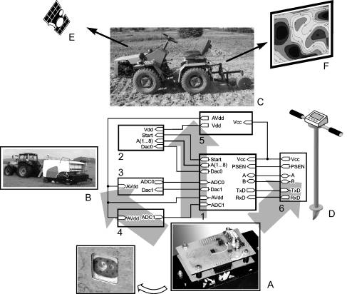
Fig 1. Structural variants of the intelligent sensor system for precision
agriculture (A–F) and its functional scheme: 1 — microcontroller for
information management and procession; 2 — control circuit of LEDs; 3 —
photo receiver connecting circuit; 4 — temperature control circuit; 5 –
source of secondary voltages; 6 — COM port connector assembly.
The worked out mobile sensor system for soil control has the following
basic parameters: the volume of the measured information image —
8 parameters (violet light — 400 nm; blue — 470 nm;
green – 520 nm; yellow — 590 nm; orange — 610 nm; red — 630
nm; IR emission; white colour); duration of soil information image development
is equal to 115 ms (8 information pulses by 10 ms having time
gaps between pulses by 5 ms); periodicity of development of information
soil images is equal to 1 s, and this makes it possible to obtain the spatial
resolution of the order of 0.5 m with the minimal transportation speed 2 km/h.
Quantity of spectral control points n
is linked with irregularity scale q
of soil reflection by the optical range with the following correlation:
n ≥ cΔλ/q, (1)
wherein
c >1 is a constant, Δλ is the optical range width. By
taking into account that value q can
hardly be analyzed and determined, the sensor system modification has been
worked out, where control points do not match up with a certain colour, but
they are uniformly placed along the spectral range. LEDs having the emission wave of 405; 460; 505; 530; 570; 620; 660 nm are used for such a variant of the sensor system.
The intelligent sensor system has structurally been executed in the form
of a unified module (A), which is built into an agricultural machinery put into
the soil. With the aim of aligning the soil monitoring procedure with
performance of a technological operation the sensor module is used as a part of
agricultural assembly (B). Sensor control is also carried out with the aid of a
developed autonomous mobile system in the form of trailed device (C) to a
mini-tractor. Besides, small-size device (D) is a modified construction of the
intelligent sensor system for small farms. The intelligent system is provided
with satellite navigation equipment (E), what makes it possible to determine
geographic coordinates of soil control points and use the monitoring results
for development of high precision electronic soil charts (F).
Identification of information images in the
intelligent sensor soil control technology. Identification of the formed information images
is one of the most complicated operations of soil monitoring intelligent
technology. In the given case identification of a light and colour sensor image
of the soil is understood as comparison of a soil sample represented by the obtained
set of brightness factors for various wavelengths of optical emission according
to a certain rule, with one of reference samples from their fixed list [2].
As the decisive rule a method of choosing the closest reference sample is used
according to the smallest value of the Euclid distance:
D(Xi, Xj) = {ΣAj(xik – xjk)2}1/2, (2)
wherein
D is the Euclid distance; Aj are weight factors; xi, xj are respective brightness factors for the
reference and the soil sample under study. Weigh factors are selected pro rata
to the values of brightness factor of the controlled soil samples.
A palette consisting of 10 ´ 10 colour cells has
been worked out for obtaining the reference colour samples, and being so, main
polygrahic colours of the CMYK standard system (C — cyan; M —
magenta; Y — yellow; K — black) are provided in angular palette
cells. Rest colours of the palette cells represent the mixture of main colours
of the CMYK system, when one colour diminishes and another colour increases by
10% during transition from one cell to another one. Besides, rules of colour
tints (by 10 cells) have been obtained which most closely approach the main
tints of soil samples. Colour saturation in every rule uniformly diminishes
along with gradual transition to white colour (colour saturation decrease is
equal to 10% in every subsequent cell). The given system of reference colour
images has been chosen because, if the precise identification of the palette
colour and, respectively, the colour tint of the soil, are required, the system
of named colours may be used, for example, Pantone (R).
The worked out palette was used for obtaining the surfaces having the
reflection factors values for every colour of the optical emission (fig. 2).
By comparing the system of reflection factors in soil samples and reference
surfaces with the aid of expression (2) the value of Euclid distance was
determined. The coloured palette cell in accordance with the tint of the soil
under study was chosen according to the minimal value of this distance. For example,
cell 1 located in the second row from “KM” line and “KY” line corresponds to
the colour of the dark grey colour, and cell 2 located in the fourth row from
“KM” line and in the third row of “KY” line corresponds to the colour of the
light grey colour. So, the colour of the soil under study is determined
according to the values of reflection factors obtained with the use of the
worked out sensor system. This makes it possible to identify a soil by a set of
reference soil samples, and the information about their quality is contained in
the data base of the intelligent system.
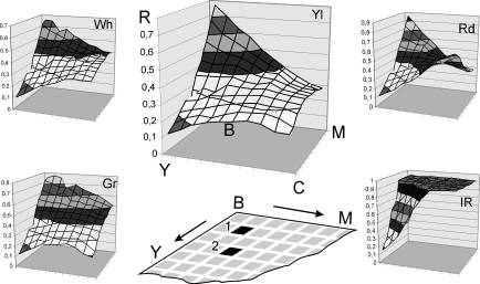
Fig. 2. Dependencies of optical
emission reflection factors having different wavelengths from reference surface
colour: Yl — yellow colour; Rd — red; Gr — green; IR — infrared emission; soil
samples identification results: 1, 2 — dark grey and light grey soils respectively.
References
1. Koleshko V. M., Gulay A. V.
et. al., 2006. Theoretical and applied mechanics, BNTU.
Minsk, issue 20, pp. 198–208.
2. Koleshko V. M., Gulay A. V.
et. al., 2007. Theoretical and applied mechanics, BNTU.
Minsk, issue 22, pp. 279–286.