Технические
науки/ Механика
Dr Achhaibar Singh1, Dr Nickolay Zosimovych2
1Amity University,
Uttar Pradesh, India
2University of South
Wales, Pontypridd, UK
LAMINAR FLOW INVESTIGATION BETWEEN A STATIONARY AND A ROTATING
DISK WITH A SOURCE AT CENTRE
The present study predicts the flow field and the pressure distribution for
a laminar flow in the gap between a stationary and a rotating disk. The fluid
enters the gap between two concentric disks at the centre of the disks and
diverges to the outer periphery. The closed form solutions for radial velocity,
tangential velocity and pressure are obtained by simplifying the Navier Stokes
equations. The velocity and pressure distributions are compared with the
experimental data of other investigators. The theoretical and the experimental
results are found in good agreement. The present solutions deviate from the
experimental results at high rotational Reynolds number. The flow separation
has been predicted near the stationery disk due to the effect of centrifugal
force.
Keywords: Disks;
Inertia; Laminar; Viscous.
I. Introduction. The flow between two disks is a topic of much interest to mathematicians as
well as to engineers. This problem allows a similarity solution with a
potential of a multiplicity of the solutions, a matter of great interest to
theoreticians. The present flow finds several applications such as face seals,
disk type heat exchangers, centrifugal manometers, turbo machines and
lubrication. Therefore, it is equally interesting to the engineers.
Lee and Lin [1] simplified the Navier Stokes equations and obtained
expressions for pressure distribution for the inward flow between two
stationary disks. They used a linearization technique to obtain pressure
without deriving expression for velocity. Wang et al. [2] investigated the flow
between shear-force pump with multiple corotating disks numerically as well as
experimentally. The significant friction loss was caused by the long flow path
due to strong recirculation in the diffuser and scroll volute, which was found
in the simulation results for the internal flow in the whole pump system. In
addition, a reverse flow appeared in the rotor part at a low flow coefficient,
which significantly deteriorated the rotor performance. Biswas et al. [3]
carried out numerical investigation of outward flow between two stationary
disks. The flow field consists of several features like toroidal recirculation,
annular separation bubble and flow reattachment. Numerical investigation was
performed by Al-Shannag et al. [4] on isothermal laminar flow of air between
two corotating confined in a fixed cylindrical enclosure. There is flow
exchange from the disks space and housing space through the clearance. They
showed that increasing gap size decreases disk surface shear and the associated
disk torque coefficient, but at the cost of destabilizing the inter-disk flow.
The outward
flow between two stationary disks has been of much interest in connection with
lubrication technology where viscous forces were predominant as compared to
inertia forces. McGinn [5] employed dye injection technique to investigate
streamline configuration, flow separation, and cavitation. Several
investigators carried out theoretical study using Karman’s momentum integral
method and power series method for the outward laminar flow [6-7]. Moller [8]
investigated laminar and turbulent flows experimentally and theoretically. He
concluded that the viscous sublayer thickening was the cause of
relaminarization of the flow.
Aim of the
present study is to derive the closed form solutions for velocity and pressure
distributions by simplifying the Navier Stokes equations. The closed form
solutions are compared with the published experimental data of other
investigators. The parametric study has been carried out to understand the
effect of the through flow Reynolds number, the rotational Reynolds number and
the gap ratio on the outward flow between a stationary and a rotating disk.
II. Mathematical Model. The geometry and the coordinate system are shown in Fig. 1. Two parallel
disks of outer radius ![]() one stationary and the other rotating with a
constant angular speed are kept h distance apart. The gap between the disks is
small as compared to the outer radius. Therefore, the axial component of the flow
velocity is negligibly small as compared to the radial and the tangential
components. The fluid enters the radial channel through a hole at the center of
the disks and diverges towards the outer periphery. The net flow in the gap
between the disks is outward. The flow is axisymmetric, i.e., derivatives of
the variables with respect to polar coordinate are zero.
one stationary and the other rotating with a
constant angular speed are kept h distance apart. The gap between the disks is
small as compared to the outer radius. Therefore, the axial component of the flow
velocity is negligibly small as compared to the radial and the tangential
components. The fluid enters the radial channel through a hole at the center of
the disks and diverges towards the outer periphery. The net flow in the gap
between the disks is outward. The flow is axisymmetric, i.e., derivatives of
the variables with respect to polar coordinate are zero.
III. Results and Discussion.
3.1. Model of a
Control System for the Launch Vehicle. A control system of the launch vehicle is designed to maintain the required (programmed) trajectory parameters of the center of mass and around the center
of mass (Fig. 1)
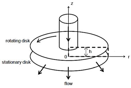
Fig. 1. Geometry and coordinate
system
The present flow
is governed by the continuity and the momentum equations in the cylindrical
coordinates:
|
|
(1) |
|
|
(2) |
|
|
(3) |
|
|
(4) |

The boundary conditions are:
|
|
(5) |
In order to get a solution for the tangential component of velocity,
Eq. (3) is reduced to an ordinary differential equation by introducing the
Karman’s similarity form as
|
|
(6) |
The substitution of the above expression
for v into Eq. (3), yields
|
|
(7) |

Equation
(7) is a second order ordinary differential equation that can be solved by
replacing, ![]() with
with ![]() where,
where, ![]() as suggested
by Lee and Lin [1]:
as suggested
by Lee and Lin [1]:
|
|
(8) |
where, 
Corresponding boundary conditions are
|
|
(9) |
The solution of Eq. (8) can be expressed
as
|
|
(10) |
Using Eqs. (6) and (10), the tangential
velocity can be written as
|
|
(11) |
The non-dimensional forms of Eqs. (11) is
given as:
|
|
|
|
|
|
|
|
(12) |

Where, 
 Here,
Here, ![]() and
and ![]() are through flow Reynolds
number,
are through flow Reynolds
number, ![]() and gap ratio,
and gap ratio, 
Eq. (12) was integrated using a second order Runge-Kutta method. The
truncation errors were limited to the order of 10-6 by choosing a step size of 0.01.
3.2. Simulating Velocities Depends on Through
Flow Reynolds Number.
Non-dimensional tangential velocity depends on through flow
Reynolds number, gap ratio and radial location (Eq. (11)). The tangential
velocity at Req = 286624 is compared with the
published experimental data [9]
and is found reasonably in good accord with the experimental result (Fig. 2).
The angular velocity of the fluid, away from the rotating disk, decreases with
the increase in through flow Reynolds number. Radial convection of tangential
velocity can be observed in Fig. 3 where the tangential velocity increases near
the stationary disk in the direction of flow. The dominance of through flow
decreases axial convection of the tangential momentum. With increase in gap
ratio, the tangential velocity decreases near the stationary disk and increases
near the rotating disk (Fig. 4).
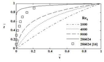
Fig. 2.
Tangential velocity distribution for different
Reø=50000, g=0.03, ![]()
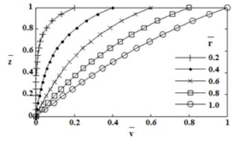
Fig. 3.
Tangential velocity distribution for Req=1000, g=0.03
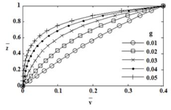
Fig. 4.
Tangential velocity distribution for Req=1000, ![]()
Figure 5 presents the radial velocity profile for different through flow
Reynolds numbers at a fixed rotational Reynolds number of 8000, a gap ratio of
0.02 and a radial position of 0.7. The centrifugal force imparts additional
momentum to the fluid near the rotating disk. As a result, the fluid near the
rotating disk moves faster than the fluid near the stationary disk. Therefore,
the maximum radial velocity shifts toward the rotating disk despite the
symmetric boundary condition for radial velocity.
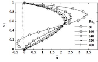
Fig.5. Radial velocity
distribution for
Reø=8000, g=0.02, ![]()
The plots of radial velocity profile at
different gap ratios, for Req=10, Reø= 1000, ![]() =0.9, show an increase in the back flow region with an increase
in the gap ratio (Fig. 6). As gap ratio
increases the radial velocity becomes asymmetric and further increase in the
gap ratio results in flow separation and backflow at stationary disk.
=0.9, show an increase in the back flow region with an increase
in the gap ratio (Fig. 6). As gap ratio
increases the radial velocity becomes asymmetric and further increase in the
gap ratio results in flow separation and backflow at stationary disk.
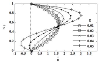
Fig. 6. Radial velocity distribution for Req=10, Reø=1000, ![]()
Figure 7 compares the experimental results [10]
with the present solution for Req=41, Reø=12279, g=0.0046. It is evident
from the figure that both the results are in good agreement. According to the Eq. (12), the pressure consists
of the pressure drop due to viscous dissipation, convective inertia and rotational inertia. The figure indicates that the rotational inertia
dominates the viscous dissipation and convective inertia resulting in negative
pressure drop. As through flow Reynolds number increases the effect of
rotational inertia decreases and the pressure drop becomes positive everywhere in the radial channel for Req=100.
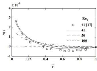
Fig. 9. Pressure distribution for Reø =12279, g=0.0046
IV. Conclusions.
The
linearization has simplified the problem resulting in the derivation of the
expressions for velocity and pressure. The present solution predicts velocity
and pressure fields that are comparable with the experimental data. The radial convection influences the
distribution of tangential velocity between the disks.
The
centrifugal force causes backflow near the stationary disk. An increase in the
through flow Reynolds number decreases the backflow and an increase in the gap
ratio enhances the backflow. The backflow decreases in the direction of flow
due to a decrease in the centrifugal force.
The pressure drop increases with a decrease in the through flow Reynolds
number as well as the gap ratio due to high viscous losses. An increased
rotational Reynolds number increases the flow path resulting in high viscous
losses that causes the pressure drop to increase.
References
1. Lee P.M. and Lin S. Pressure distribution for
radially inflow between narrowly spaced disks, Trans. ASME J. Fluids Engg.,
No107, pp. 338-341, 1985.
2. Wang B., Okamoto K., Yamaguchi K., Teramoto S.
Loss
mechanisms in shear-force pump with multiple corotating disks, ASME J. Fluids Eng., No136, pp.
081101-1-081101-10, 2014.
3. Biswas N., Manna N. K.,
Mukhopadhyay A., Sen S. Numerical simulation of laminar confined
radial flow between parallel circular discs, ASME J. Fluids Eng., No134, pp.
011205-1- 011205-8, 2012.
4. Al-Shannag M., Herrero J., Humphrey J. A. C.,
Giralt F. Effect of radial clearance on the flow between corotating disks in
fixed cylindrical enclosures, ASME J. Fluids Eng., No124, pp. 719–727, 2002.
5. McGinn J. H. Observations on the radial flow
of water between fixed parallel plates, Applied Scientific Research, No5, pp. 255-264,
1956.
6. Woolard H. W. A theoretical analysis of the viscous flow in a narrowly spaced
radial diffuser, ASME J. Appl. Mech., No24, pp. 9-15, 1957.
7. Savage S. B. Laminar radial flow between
parallel plates, ASME J. Appl. Mech., No31, pp. 594-596, 1964.
8. Moller P. S. Radial flow without swirl between
parallel disks, Aeronaut. Quart., No14, pp. 163-186, 1963.
9. Bayley F. J., Owen J. M. Flow between a
rotating and a stationary disk, Aeronaut. Quart., No20, pp.333-341, 1969.
10. Szeri A.
Z., Adam M. L. Laminar through flow between closely spaced rotating disks, J.
Fluid Mech., No86, pp. 1-14, 1978.