S.F.Jatsun,
the professor, the manager. Chair of theoretical mechanics and mechatronics, SWGU
(an e-mail: teormeh@inbox.ru)
N.P.
Uvarova, Associate Professor at the
Theoretical Mechanics and Mechatronics Department, SWGU (an e-mail:
teormeh@inbox.ru)
A.N.Rukavitsyn,
Associate Professor at the Theoretical
Mechanics and Mechatronics Department, SWGU (an e-mail: alruk75@mail.ru).
RESEARCH OF OPERATED MOVEMENT OF THE JUMPING MINIROBOT
Mobile
transport devices of jumping type
(jumping robots) are objects of research of many scientists as at movement on
strong a cross-country terrain the spasmodic way of moving is more convenient
than sliding or rotation. As the natural approach at creation of similar robots
copying of movement of the small animals capable slowly to accumulate energy in
muscles and then serves, during a jump, quickly it to liberate. Such devices
are presented in works [1,2]. Jumping up of the similar robot is provided with
the spring drive containing the mechanism of a platoon of springs. Flight
begins when the potential energy saved up in a spring will be transformed to
kinetic energy of the case.
Other
approach is based on application of the mobile internal weights which are built
in the case of the robot. Mechanisms of this type can move on a surface without
a separation, features of their movement are shined in work [3], and also in
work [4].
In [5]
the mobile devices moving with a separation from a surface at the expense of
periodic movement of internal weight are presented. Difference of such devices
from robots with spring drives is that as a movement source potential energy of
a spring is used not, and kinetic energy of moving weights which will be
transformed to kinetic energy of the jumping case. It allows to carry out
traffic control at the expense of change of one parameter – angular speed of
rotation debalance.
At the same time methods of calculation of the systems using for
movement kinetic energy of internal weights, are developed insufficiently.
Therefore the purpose of the given work is working out of mathematical model of
movement of the jumping robot of the new type containing one rotating weight,
and studying of the basic laws of operated movement.
The
considered jumping minirobot represents the mechanical system consisting of two
firm bodies, one of which – the cylindrical case in weight m1 – periodically contacts to a rough surface, and the
second – debalance in weight m2
– in regular intervals rotates concerning the case (fig. 1).
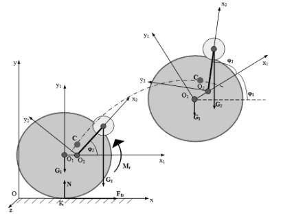
Fig. 1 Settlement scheme of movement of the jumping minirobot
On the
scheme point О1 – the case
center of gravity; through point О2
passes a rotation axis of debalance. The center of weights of the robot – a
point C. As operating parameter in
considered system frequency of debalance rotation ω, and operated – height, length of a jump and average speed
of movement of the robot acts. The relation of weights of elements of system λ=m2/(m1+m2) is the varied parameter.
Let's
consider movement in motionless system of coordinates Oxyz. We will rigidly connect with links of the robot two mobile
systems of coordinates: one of which axes passes system O1x1y1z1 which axes are
the main central axes of inertia of the case, and system O2x2y2z2, through a
point modeling debalance.
Let's
admit that all points of system move in parallel vertical planes. It is
possible, if the plane of relative rotation debalance coincides with a plane of
material symmetry of the case. Then, choosing an axis of abscisses of
motionless system parallel to movement, it is enough to consider movement of a
projection of the robot in plane Oxy.
Relative
movement of debalance is set, it occurs to constant angular speed ![]() , and it is possible to present an angle of rotation in the form φ2=ωt.
, and it is possible to present an angle of rotation in the form φ2=ωt.
Let's
enter into consideration radiuses-vectors ![]() ,
, ![]() ,
, ![]() , coordinates of the centers of gravity of the case defining in absolute
system and debalance, and also coordinates of the center of weights of all
system of S. Obviously that
, coordinates of the centers of gravity of the case defining in absolute
system and debalance, and also coordinates of the center of weights of all
system of S. Obviously that
![]() , (1)
, (1)
where ![]() – radius-vector of debalance concerning the case center (fig. 2).
– radius-vector of debalance concerning the case center (fig. 2).
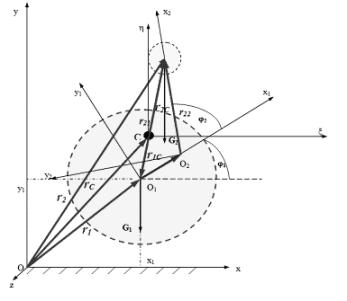
Fig. 2 Scheme of definition of position of points of vibrating system in
a movement plane
From definition of the center of weights of system, using the given
vector equality, it is possible to receive expression
![]() . (2)
. (2)
Let's define vector coordinates ![]() . From the scheme on fig. 2 it is visible that it is
the sum of vectors
. From the scheme on fig. 2 it is visible that it is
the sum of vectors![]() and
and ![]() which
coordinates are convenient for setting in relative systems:
which
coordinates are convenient for setting in relative systems: ![]() – in case
system,
– in case
system, ![]() – in system of
debalance.
Hereinafter the index «Т» at a
matrix-line means transposing. Distance О1О2 and length of
debalance l are set.
– in system of
debalance.
Hereinafter the index «Т» at a
matrix-line means transposing. Distance О1О2 and length of
debalance l are set.
In absolute system vectors will be defined by means of matrixes of turn Т10 of system of
coordinates O1x1y1z1
rather Oxyz and Т21
systems O2x2y2z rather O1x1y1z1
[20]: ![]() ,
, ![]() . The top index «0»
at vectors (in brackets) specifies in absolute system of coordinates. The
required radius-vector of dot weight concerning the center of weights of the
case in absolute system of coordinates will be certain by equality:
. The top index «0»
at vectors (in brackets) specifies in absolute system of coordinates. The
required radius-vector of dot weight concerning the center of weights of the
case in absolute system of coordinates will be certain by equality:
![]() . (3)
. (3)
To radius-vector of the center of weights of the case in absolute system
there corresponds a matrix-column ![]() .
.
Movement of considered mechanical system is described
by the vector equations expressing the theorems of dynamics about change of
quantity of movement and the moment of quantity of movement of system:
![]() (4)
(4)
![]() , (5)
, (5)
where -
![]() quantity of movement;
quantity of movement; ![]() - the moment of quantity of
movement of system concerning its center of weights С;
- the moment of quantity of
movement of system concerning its center of weights С; ![]() ,
, ![]() - the main vector and the
main moment of the external forces enclosed to system.
- the main vector and the
main moment of the external forces enclosed to system.
Quantity
of movement of system by definition to equally vector sum ![]() in which,
in which, ![]() ,
, ![]() - speeds of the center of
gravity of the case of nyt robot and debalance, and its derivative on time
- speeds of the center of
gravity of the case of nyt robot and debalance, and its derivative on time ![]() . Acceleration of the center of
weights of the case is presented by a vector
. Acceleration of the center of
weights of the case is presented by a vector ![]() , and acceleration of debalance, according to (1), the sum
, and acceleration of debalance, according to (1), the sum ![]() .
.
Acceleration
of debalance in its movement round point О1
we will receive, differentiating the equation (3):
![]() .
.
Substituting
values of derivative matrixes and vectors in (4) and passing from the vector
form to scalar, we will find the differential equations of movement of the
center of weights of the case:
![]()
![]()
![]() ;
;
![]()
![]()
![]() .
.
Derivatives of an angle of rotation of the case present at the received
equations we will define by means of the theorem of change of the moment of
quantity of movement of system (5).
Let's
dwell upon procedure of a finding of the kinetic moments. The choice as the
center of reduction of the center of weights of system isn't casual, as in that
case in the total equation of rotation there are no accelerations of the center
of weights of the case.
The
center of weights of the robot is a mobile point. We will connect with it
system of coordinates Сξηζ, which axes move is forward, that
is all time remain parallel to axes of motionless system. In this system of
coordinates we will define the sizes entering into the theorem of the moments
(5), and we will notice that angular characteristics of movement of the robot,
considered in system of the center of weights and in motionless system,
coincide.
The kinetic moment of system is the vector sum:
![]() . (6)
. (6)
The kinetic moment of the case develops of the kinetic moment of its
rotation round own center of weights and the moment of quantity of movement of
the center of weights of the case (as the material point which weight is equal
to weight of the case) concerning the general center of weights:
![]() . (7)
. (7)
![]() – the kinetic moment of the case
concerning its center of gravity О1,
– the kinetic moment of the case
concerning its center of gravity О1,
![]() – a vector of angular speed of the robot, J – a tensor of inertia of the case in system of the axes parallel
to axes of motionless system.
– a vector of angular speed of the robot, J – a tensor of inertia of the case in system of the axes parallel
to axes of motionless system.
It is
known that the most simple kind accepts an inertia tensor in system of the main
axes of inertia, that is system O1x1y1z1:
 ,
,
where
elements of the main diagonal – the axial moments of inertia of the case – are
set. From here through a matrix of turn Т10
it is possible to pass in system of the axes parallel motionless, in which
tensor of inertia becomes
![]() .
.
The
kinetic moment of debalance, modelled in our case as a material point, by
definition is equal:
![]() (9)
(9)
Generalizing (6) - (9), considering representation of speeds of points
of a body and definition of the center of weights of system, the kinetic moment
of system we will write down in a kind:
![]() . (10)
. (10)
Starting with (1) and (2), we will present radiuses-vectors of points of
system concerning the center of weights in a kind:
![]() . (11)
. (11)
Differentiating (10) on time and considering (11), we will come to
expression:
![]() .
.
In view of that
the main moment of external gravity concerning the center of weights is equal
to zero, substituting the coordinates of vectors received in the course of
transformations in (5) and passing to the scalar form, we will receive
therequired differential equation of rotation:.
![]() .
.
Thus,
we come to system of the differential equations of movement of the robot:
 (12)
(12)
Where constant factors are expressed through system parameters:
![]() .
.
The
system of three differential equations (12) describes robot movement in flight, that is when the center of symmetry of the case coincides with
the center of weights the condition is satisfied y1> R, where R –
case radius.
For a
complete description of movement by means of jumps the system (12) it is
necessary to add movements with the equations of movement of the robot on a
basic surface, and also to define change of parameters of movement at landing
and a separation. As an analytical condition of movement on a flat basic
surface equality y1=R
serves.
Let's
notice that the movement equations on a surface can be received by means of
already specified theorems (4), (5), considering that to gravity operating on
system normal reaction ![]() , force dry Kulon’s friction
, force dry Kulon’s friction ![]() and the resistance moment of
rotation
and the resistance moment of
rotation ![]() (fig. 1) are added. If to admit
absence rotation of cases the quantity of the equations will be reduced to two:
(fig. 1) are added. If to admit
absence rotation of cases the quantity of the equations will be reduced to two:
 (13)
(13)
Force of a dry friction is defined according to analytical model:
where F0 – a projection equally
effective all applied to a design of the robot of forces, except force of a dry
friction; f0 – factor of a dry friction; N –
normal reaction of a surface; ![]() – speed of the robot along axis Ox.
– speed of the robot along axis Ox.
At the
moment of a landing speed of a point of a contact changes a direction, that is,
the system has blow. Within the limits of the given research we will be limited
to a case when kinetic energy of system, except for energy of own rotation of debalance,
at blow is lost. It means that as a result of a landing of the robot speed of a
point of a contact and angular speed of the case will receive zero values which
we will accept as initial, by consideration of the following phase of movement.
Let's study influence of the operating parameter on characteristics of
movement of the robot. We will address to the received system of the
differential equations of movement of the robot in air. The first equation –
the rotation equation – as the equation of the first order concerning speed has
the obvious analytical decision which under zero entry conditions takes a form:
![]() . (14)
. (14)
Thus,
clearly that change of speed of rotation in time is presented by the periodic
limited continuous function which frequency coincides with frequency of
rotation of debalance. Besides, expression (14) doesn't change the sign.
Really, for the least value of a denominator of the fraction which are in
brackets, we have:
![]() .
.
The
denominator is positive. But, as A+B≥B+Acosωt>0,
the sign on angular speed, obviously, will coincide on a sign with speed of
rotation of debalance.
In that
specific case, if the factor A is
equal in system (12) of the equations to zero, angular speed of rotation
remains to a constant. For the considered robot the similar case takes place,
if centers O1 and О2 coincide. It means that,
coming off a surface with zero angular speed, the case in the further flight
doesn't rotate, and it can be considered as a material point in weight М=m1+m2, moving under the
influence of force F=m2ω2l which vector in
regular intervals rotates with angular speed ω.
Let's consider the flight of a point
occurring at the expense of action of force F
of a variable direction ( Fig. 3). Entry conditions of such movement are
defined by a condition of a point at the moment of a separation from a surface,
namely: in the zero speed and some nonzero corner α a force inclination.
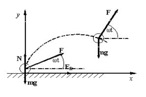
Fig. 3 Scheme of the forces operating on a material
point
In case
of a separation normal reaction is equal 0, i.e., equality is carried out
 . (15)
It is
obvious that, depending on parameters of system the equation (15) can not have
decisions, have the unique decision or set of decisions. So, if values of
parameters satisfy to an inequality  , (15) has no decisions, the point doesn't come off a surface. In the
second case when for values equality is carried out,
, (15) has no decisions, the point doesn't come off a surface. In the
second case when for values equality is carried out,  (15) has the unique
decision. Nevertheless, the further lifting of a point in this case won't
occur, as its acceleration will not reach necessary positive value. In the
third case the area of values of parameters of system is defined by an unequal
(15) has the unique
decision. Nevertheless, the further lifting of a point in this case won't
occur, as its acceleration will not reach necessary positive value. In the
third case the area of values of parameters of system is defined by an unequal
 . (16)
In this
case reaction addresses in a zero at value of an angle of slope of force
(hence, and an angle of rotation of balance)

Proceeding
from definition of return trigonometrical functions, the separation corner lies
in an interval ![]() .
.
Further we will consider vertical movement of the case, neglecting its
rotation. If time reference mark to connect with the separation moment movement
of the center of weights of the case will be described by the differential
equation:
 (17)
(17)
Let's show that there is a time interval in
a start of motion, on which acceleration of point positively. Really, if to
transform (17) to product:
![]() ,
,
that is
obvious that on a time interval ![]() acceleration is more than zero
thanks to what the point after a separation will continue movement upwards.
Having integrated twice the equation (17) taking into account zero entry
conditions, we will receive that at it is possible to present coordinate in the
form of the sum
acceleration is more than zero
thanks to what the point after a separation will continue movement upwards.
Having integrated twice the equation (17) taking into account zero entry
conditions, we will receive that at it is possible to present coordinate in the
form of the sum
![]() ,
,
where  – limited from above the value
 , square-law function of time monotonously decreasing on an interval
  l,
l,
![]() – the limited periodic function.
– the limited periodic function.
It allows
to assert that the coordinate is limited from above. Character of change of
function y1(t) says that the point will by all means
fall and will concern a surface.
Similarly from the differential equation
 ,
,
considering
zero entry conditions, we receive the law of change of an absciss, which also
can be presented in the form of the sum of infinitely decreasing linear
function  and the limited periodic
function
and the limited periodic
function![]() . Therefore it is obvious that since some moment of time the coordinate
will accept the values opposite on a sign of angular speed of rotation of debalance.
. Therefore it is obvious that since some moment of time the coordinate
will accept the values opposite on a sign of angular speed of rotation of debalance.
The analytical dependences received in given section for coordinates
were investigated in addition, at numerical modeling of movement of the robot.
Let's
consider behavior of system for various values of the operating parameter ω. We will result some results of
numerical modeling of movement of the robot. At calculations following values
of parameters of system have been accepted: m1=0.05
kg, m2=0.01 kg, l=0.01 m, О1О2=0 m. the Size of angular speed of
rotation of debalance changed for reception of various trajectories. We will
notice that from an inequality (16) follows that for a separation of the robot
from a surface angular speed of debalance can't be low 80 radian in a second.
On fig.
4 trajectories of movement of the robot are resulted at three various values of
speeds of rotation of debalance. Following laws are obvious. First, as well as
the direction of movement of the robot opposite on a sign to a rotation
direction of debalance was supposed earlier. Secondly, with growth of angular
frequency of debalance the movement trajectory in air becomes complicated, on
it there are the self-crossing points which quantity grows with frequency
increase. Thirdly, together with frequency from a surface, length of a step –
distance the maximum height of lifting of the robot increases by surfaces
between points of a separation and the subsequent landing.
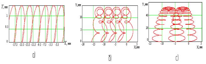
Fig. 4 Trajectory of the robot:
ω =100 s-1; b - ω =300 s-1; c - ω =600s-1.
Dependence
of coordinate at from time is presented by the sum of two functions: square-law
y1(t) and harmonious y2(t).
Let's consider top ordinate as function of parameters of system:
 , (18)
where
the dimensionless parameter  ,
, ![]() , is equal to the weight relation of weight of debalance to all robot weight.
, is equal to the weight relation of weight of debalance to all robot weight.
On the
basis of (18) schedules of analytical dependences of the maximum height of
lifting from angular frequency of debalance ![]() (fig. 5а) and from the relation
of weights
(fig. 5а) and from the relation
of weights ![]() (fig. 5б) have been constructed.
These schedules in both cases are designated by figure I. Triangles under figure II
in drawing designate the maximum values of lifting for separate ω and λ, defined by numerical calculations.
(fig. 5б) have been constructed.
These schedules in both cases are designated by figure I. Triangles under figure II
in drawing designate the maximum values of lifting for separate ω and λ, defined by numerical calculations.
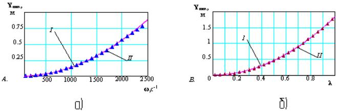
Fig. 5 Dependence of the maximum height of lifting of
the robot on angular speed of rotation дебаланса (a) and from the relation of
weights (b)
Let's
notice that increasing character y1max(λ) is obvious from (18) while y1max(ω) as function can
have the maximum or minimum value. Really, the private derivative  has two valid roots,
  and
and , and one point of rupture ω=0.
Investigating a derivative sign on set of the valid values ω, we receive that first two values correspond to local
minima, and in a point of rupture of a derivative the local maximum on
frequency takes place. On set of frequencies
, and one point of rupture ω=0.
Investigating a derivative sign on set of the valid values ω, we receive that first two values correspond to local
minima, and in a point of rupture of a derivative the local maximum on
frequency takes place. On set of frequencies  function y1max(ω) isn't limited from
above. From this that any value, obviously, satisfies to an inequality (16)
which characterizes area of parameters at which the separation from a surface
is possible, the conclusion about limitlessness of growth of the maximum height
of lifting with increase in speed of rotation of debalance from here follows.
function y1max(ω) isn't limited from
above. From this that any value, obviously, satisfies to an inequality (16)
which characterizes area of parameters at which the separation from a surface
is possible, the conclusion about limitlessness of growth of the maximum height
of lifting with increase in speed of rotation of debalance from here follows.
The Fig. 6 shows results of numerical definition of dependence of height
of lifting from the frequency, the parities of weights received for three
various sizes.
Apparently,
the increase in a parity of weights leads to fast growth of the maximum height
of lifting of the robot. To the same conclusion it is possible to come,
analyzing properties of function (18). Similar communication of height of debalance
l is here too obvious the resulted
length.
Besides
lifting height, dependences of length of a step of the robot – average distance
between points of a separation both the subsequent landing – and average speed
of moving – relations of total length of the calculated steps up the time of
their passage from frequency have been numerically investigated. On fig. 6,7
corresponding schedules are presented.
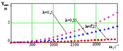
Fig. 6 Dependence of height of lifting on frequency at
various λ
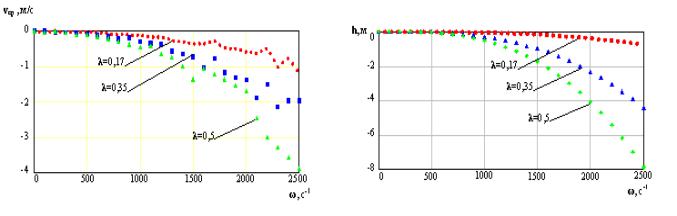
Fig. 8 Dependence of length and average speed of a jump from frequency
at various λ
The analysis
of dependences leads to conclusions that the length of a jump, as well as
height, monotonously increases with growth of parameters ω and λ.
Average speed of moving also increases, but character of its change
nonmonotonic that is connected with presence in movement of two making - flight
and movement on a surface. On a surface the robot on a condition is motionless,
duration of its stay in rest depends on a system condition (in particular, from
a rotation phase of debalance) at the moment of landing.
Thus,
in the given work the scheme of the mobile two-mass mechanical system, capable
to move on a firm rough surface with a separation from it is considered.
Developed the mathematical model and the differential equations, allow to
describe robot movement in a phase of flight and in a finding phase on a basic
surface. The analysis of the received equations has shown that the height and
length of a jump are monotonously increasing functions of operating frequency
of rotation. As a result of calculations it is established that the form of a
trajectory of the center of the case depends on size of the operating
parameter. Also dependence of a direction of movement of the robot on a
rotation direction of debalance is revealed, and dependences of height and
length of a jump from frequency of rotation and the relation of weights of
system are defined.
Work is executed within the limits of
realization of the Federal target program « Научные и научно-педагогические кадры инновационной России на 2009-2013 годы».
THE LIST OF REFERENCES
1.
Kesner S., Plante J.-S.,
Dubovsky S., Boston P. A hopping mobility concept for a rough terrain search
and rescue robot // Advances in
Climbing and Walking Robots. Proceedings of 10th International Conference
(CLAWAR 2007). Singapore. Pp. 271-280.
2.
Miyazaki M., Hirai S. Jumping via robot
body deformation – Mechanics and mechanism for higher jumping // Advances in
Mobile robotics. Proceedings of the 11 International Conference on Climbing and
Walking Robots and the Support Technologies for Mobile Machines. Coimbra.
Portugal, 2008. Pp.373-380.
3.
Larin V.B., Matiyasevich V.M. Concerning the
designing of the hopping apparatus // Proceedings of the Fifth International
Conference on Climbing and Walking Robots and their Supporting Technologies
CLAWAR 2002. Pp.365-372.
4.
Черноусько Ф.Л.
О движении тела, содержащего подвижную внутреннюю массу // ДАН. 2005. Т.405. № 1. С. 1-5.
5. Jatsun S., Dyshenko V., Yatsun A.,
Malchikov A. Modelling of Robot̕s Motion by Use of
Vibration of Internal Masses // Proceedings of EUCOMES 08. Pp.267-274.