ТЕХНИЧЕСКИЕ
НАУКИ/ 5. Энергетика
Shishka N.V., Candidate of Physico-mathematical Sciences Kuleshova E.O.
National Research Tomsk Polytechnic University
The description of the one-machine power supply system
by means of transfer
function
Simulation of the linearized equations of the
system of regulation of power supply systems in
MatLab Simulink through transfer functions does
not require reception of the characteristic equation the
conclusion of which, as a rule, is not made in polynomial form
for complex power supply systems, as a rule, because of
excessive complexity of mathematical transformations. It provides
the way to investigate complete transient phenomena in power supply systems
more detailed.
Introduction
Nowadays all manufacture, the
basic part of distribution and consumption
electricity in power supply systems are carried out on an
alternating current. Therefore, the
frequency, size and the voltage form of
pressure have got values of the parameters describing the quality of the
electric power. It is necessary to
calculate the static stability of power supply system to form a
system of differential equations of transients
and linearization of these equations hold in order. Altogether
these equations make mathematical model of a power supply system.
Mathematical model of a power supply system
For
the description of a power supply system by means of transfer functions let us
consider an one-machine power supply system (fig. 1) the synchronous generator
of which is equipped by an automatic
regulator of excitation strong action (ARE
SA). [1].
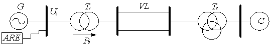
Fig.
1. The diagram of an one-machine power supply system.
The basic linearized equations of transients an
one-machine power supply system with ARE SA look like [1, 2]:
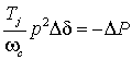
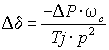
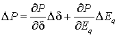
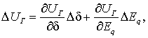
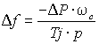 ,
, 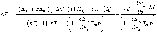 .
.
In the process of linearization of the regulatory system, all variables are expressed in deviations from steady-state values assigned to the nominal
values. So we take as parameters to control the error voltage
vector generator voltage Ug, and the rotation frequency f of the generator
rotor.
The simulation of an
one-machine power supply system through transfer functions [3] (fig. 2), describing the given object, will
be executed in the environment of Matlab Simulink [4].
The coefficients of
transfer functions were calculated for the following types of electrical
equipment and parameters with the help of the software package MathCad [5]:
The generator G
is the equivalent of two turbo-generators such as DVT-200-2UZ. The transformer T1
is the equivalent of two types of transformers TDTS-250000/220. Transformer T2
is the equivalent of two groups of single-phase transformer type ATDTSTN-250000/220/110.
Line VL
- double circuit, the wire is made with the cable ASO-300 which has a length of
200 km. System C: Uc = 115 kV. The turbine of an equivalent generator is: the regime
of Pm(1)
= 0.5Pmax. Gate factors ARV: K0U = 100 unit.
exc. x * s / unit.
voltage. K1U = 10 unit. exc. x * s
/ unit. voltage., K0f, K1f.
The generator exciter: Te =
2. The excitation controller: Tp =
0.1 s.
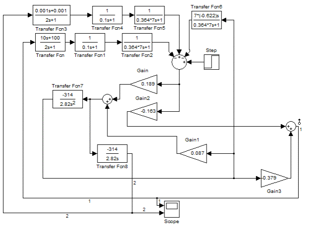
Fig. 2. The diagram of
an one-machine power supply system in MatLab
Charts of transient are
resulted on fig. 3.
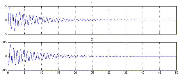
Fig. 3. Charts of errors
1 - the voltage and 2 – the frequency
From Fig. 3 you can see
that the deviation of the voltage and frequency from
the set of values tends
to zero, consequently, the system is stable. The time constant of the transient
phenomena is an average of 10-14 s.
Conclusion
A block scheme of the one-machine
power supply system with ARE SA is obtained. The simulation of the system in MatLab Simulink is produced. The quality
of electricity can be judged by the process of changing the frequency in the
power system. At the initial stage of the transition the frequency
ranges 49,5-50,5 Hz, which is valid for a short-term operation. In a normal
mode, the frequency must be maintained with an accuracy Hz. As can be seen from
the graphs, the model fulfills this condition completely.
References
1.
Хрущев
Ю.В. Методы расчета устойчивости энергосистем. Учебное пособие. – Томск: Изд-во
ТПУ, 2005. – 176 с.
2.
Электромеханические
переходные процессы в электроэнергетических системах: учебное пособие/ Ю. В.
Хрущев, К. И. Заподовников, А. Ю. Ушков; Томский политехнический университет. –
Томск: Изд-во Томского политехнического университета, 2010. –160 с.
3.
Коновалов
Б.И., Лебедев Ю.М. Теория автоматического
управления: Учебное методическое пособие. — Томск: Факультет
дистанционного обучения, ТУСУР, 2010. —
162 с.
4.
Лазарев
Ю. Моделирование процессов и систем в MATLAB. Учебный курс. – СПб.: Питер, Киев: Издательская группа BHV, 2005 – 512 с.: ил.
5.
Ивановский
Р. И. Компьютерные технологии в науки и образовании. Практика применения
системы MathCAD Pro: Учеб. пособие/Р. И. Ивановский. – М.: Высш. шк., 2003. –
431с.: ил.