Romaniuk S. O., Romaniuk O. N., Piddubetska M. P.
Vinnytsia National Technical University
BASIC
ANALYSIS OF TEXTURE FILTERING METHODS
In this article the main methods texture
filtering are treated: point sampling,
bilinear filtering, trilinear, anisotropic filtering. The
basic principles, the classification, the main
advantages and disadvantages of these
methods of filtration are describes.
Key words: texture, texel, point sampling,
bilinear filtering, trilinear filtering, anisotropic filtering.
One of the key issues
of modern computer graphics is increasing realistic
of images that are synthesized.
This issue is very important in solving many applied tasks. These include tasks such as: visualization system for scientific research, medical and technical diagnostics,
building visual models of processes
and phenomena, using computer graphics to create films and computer games. New technologies for 3D-visualization
are continuously developed; algorithms for increasing memory bandwidth are improved and upgraded. An important part
of a 3D-visualization is texturing.
Texture is a two-dimensional raster image
that is overlay on the surface of
the object. Texture filtering – is a mechanism that provides texture blending
to the polygons which are differ in size. Color
of pixel projection of a three-dimensional object on the screen should clearly define to color of texel
of proper texture. But this is true only in simple
cases when projecting
angles close to normal,
with the appropriate distance from
the image plane. Pixel and texel only in the
mathematical sense referred to as
point: physically they are very specific size and look
like a circle whose diameter
depends on the screen resolution of the monitor and on texture. As the projection angle is beyond the certain limits, it happens
that one pixel projected two or more texels and then the form of the projection is close to oval (Fig.
1). If the object is very close to the plane of projection - one texel
is projecting into
several pixels [1].
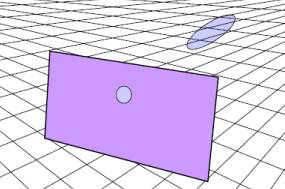
Figure
1 - The elliptical shape of the
light spot
The process of blending
textures on the surface leads to the appearance of artifacts and
methods of their elimination. This paper reviews the main methods of texture filtering: point sampling,
linear filtering, bilinear filtering,
trilinear and anisotropic
filtering (Fig. 2).
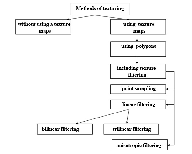
Figure 2 – The
classification of methods for texture
filtering
Analysis of the main methods of filtering
Point
Sampling –
is the easiest way to determine the
color of a pixel in texture -based image. To implement this
method you must select texel, which is closer than the others located to the center of the light spot (Fig. 3) [2].
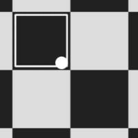
Figure 3 – Point
sampling method
The main advantage of this
method of filtration is low
demands on memory bandwidth, for determining pixel colors
you must select only one pixel of texture
memory.
The main disadvantage of this
method – is if the polygon
is located close
to the screen (or from the point of observation), the
number of pixels is greater than the number of texel leading to general deterioration of image quality If such a texture overlaid over the object that goes into the depth of the
scene, perspective effect is
greatly distorted. This method was widely used until the hardware accelerators were invented. After the distribution of hardware accelerators it
was possible to use more qualitative
methods.
Bilinear filtering - the method that uses
interpolation techniques. To determine
the texels to be involved for interpolation, commonly is used basic form of the
light spot - a circle. In fact,
the circle is approximated by four texels (Fig.
4). This filtering
method is significantly more productive than the method of point filtering, as taken
into account the shape of the light spot and used interpolation. The resulting color of pixel
is determined by blending
operation. First blended colors of two pairs of texels
on the X-axis, then two obtained colors are blended along the Y-axis. More texels are need for the interpolation than
actually available if the polygon
is approaching too close to the screen or to the observation point. As a
result blurred images are generated
with very high quality, but this is just a side
effect of this type of filtering.
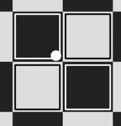
Figure 4 - The method of bilinear filtering
The main disadvantage of bilinear
filtering is that approximation
performed correctly only for
polygons that are
disposed parallel to the screen or to the observation point. If the polygon turned at an angle to the screen (which is in 99% of cases) the approximation is incorrect. In this case, it is used a circle approximation, while should be used approximation of the ellipse.
With bilinear filtering
you have to read four
texels from texture memory
to determine the color of each pixel that is displayed on the screen, which means that the demands on memory bandwidth increased four times in
comparison with a sample pointing filtration.
Trilinear filtering is a method of filtering that
combines
mip-texturing and bilinear filtering. Mip‑texturing is a method of
reducing the amount of calculations required for accurate overlay texture image
on the polygon. [3]
Trilinear filtering has the advantage of hardware simplicity and efficiency at the expense of visual quality. Instead of calculating the shape of the projected
track of light beam, this method uses
the square of filter in texture space. Blending
two bilinear filter
from adjacent map-level trilinear filtering forms
an approximate to a circle filtering area to form the area of random
size.
Trilinear filtering as bilinear uses blocks of four texels,
the color of the pixel that should be
deduced on the screen is determined by interpolating
of two mip-textures. Mip-map levels are beforehand calculated smaller versions of the original texture, which means, a qualitative approximation
of texels located in the spot
light is obtained.
The last stage is
analysis boundaries of the two blocks,
corrected any mistakes and inconsistencies at the boundaries of these two blocks. In bilinear filtering it is quite common to see lines
that occur at the boundaries of blocks that disappear when
in trilinear filtering. In
addition, trilinear filtering
is better neutralized distortions and irregularities in motion and when the
angle of observation changes.
Nowadays support of trilinear filtering has
become a standard feature in graphics
chip, because it provides the formation
of three-dimensional images with
high quality. This method has disadvantages: there are some defects at
a greater distance, because
this method was originally developed
to reduce the distortion between mip-map levels.
Images formed very efficiently only at the
direct corners of observation. In real visualization the
geometric shape of the object
can be affected.
The form of textured objects in the bilinear
and trilinear filtering
may be distorted because both of this filtering are
isotropic - the image is filtered in some form - in the form of a square. The majority of the
formed objects do
not fit into this certain and immutable form:
for their high-quality processing it is necessary to use a different type of filtering – anisotropic filtering.
The term "anisotropy"
consists of several Latin words: "an"
for not, "iso" for same, and "tropic" from tropism, relating to direction;
anisotropic filtering does not filter the same in every direction. The
name of this
technology reflects its technical implementation. Anisotropic
filtering typically operates
at least 8th texels,
using the undefined form model. As a
result, this filtering removes noise
and distortion of objects, and
the whole image is a more qualitative.
For today the best results in formation of three-dimensional scenes
provides anisotropic filtering. Texels in this
type of filter are selected
not from the symmetrical region, but taken from the perspective corrected
field (anisotropic form). The shape of this area is
not advanced, but commonly used rectangular
or trapezoidal area or areas in the form of a parallelogram - it all depends on the angle of the surface location (Fig. 5).
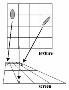
Figure 5 - The method of anisotropic
filtering for texture image
The level of filtering
is determined by the number of Texel processed in the calculation
of final pixel. At the level 1x anisotropic
filtering uses eight texels. On modern graphics
cards filtration level
can be put in the
drivers. The maximum level is
16x, but producers
do not use all the intermediate steps. The most common level
is 2x (16 Texel), 4x (32 Texel), 8x (64
Texel) and 16x (128 Texel). When the level of filtration is increases computing workload also increases.
Like bilinear and trilinear filtering,
anisotropic filtering eliminates the effects of aliasing, but
this method also reduces the degree of blur and
keeps the image details at
extreme viewing angles (Fig.
6).
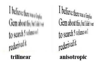
Figure 6 – The Comparison
of trilinear and anisotropic
filtering
Anisotropic filtering method
has some disadvantages: the realization of anisotropic filtering
is quite complicated and the rate of formation of dynamic scenes significantly decreases [4].
Conclusions
In this work classification and comparative analysis of
the basic methods of filtering of
texture images was carried out. Bilinear filtering requires less
time for the formation of three-dimensional scenes, but has a major
disadvantage: visible transitions
between the boundaries of mip-levels.
Best results are obtained in trilinear and anisotropic filtering, where the
transitions between mip-levels are calculated correctly. In the
near future
further development and using of anisotropic filtering is expected, which requires
further study this area in computer graphics.
Literature:
1. Гусятин В.М., Чаговец Я. В., Кожушко Д. Г. Метод анизотропной фильтрации
текстур при синтезе зображений обратным трассированием / В.М. Гусятин, Я. В.
Чаговец, Д. Г. Кожушко // Наукові праці ДонНТУ, серія
«Інформатика, кібернетика та обчислювальна техніка». – 2009.
2. Роджерс Д. Алгоритмические основы машинной графики/ Д. Роджерс: Пер. с англ. –
М.: Мир, 1989.
3. McCormack Joel, Farkas K. I., Perry R., Jouppi N. P.. Simple and Table
Feline: Fast Elliptical Lines for Anisotropic Texture Mapping. / Joel
McCormack, K. I. Farkas, R. Perry, N. P. Jouppi. Western Research Laboratory. –
1999.
4. Foley J. D., van Dam A., Feiner S. K., Hughes J. F., Computer graphics
(principles and practice)./J. D. Foley, A. van Dam, S. K. Feiner, J. F.
Hughes //Addison-Wesley Publishing
Company, Inc. – 1996.