*112893*
Anatoli M. Voronin 1, Bekmurza H.
Ajtchanov 2, Janusz Partyka3,
Aitkul Aldibekova2
1Almaty
technological University, 2Kazakhstan National Technical University named after
K.I.Satpayev, 3Lublin University of
Technology
Elements of automatic control of hydrodynamic systems
Abstract. The paper presents data on the automated system to
manage certain elements of the hydrodynamic system, relating to the production
of liquid milk. Similar systems could find application in various fields of
engineering, for example, to create hydroelectric power, oil production plants,
the control systems of various chemical industries, in the final product
containing hydrogen atoms, in the flow of propellant systems, etc., where you
want to take control hydrodynamic parameters by means of nuclear magnetic
resonance of atoms used in the relevant products.
Keywords. The automated control system, hydrodynamics,
algorithm, magnetization of milk, flap
gate, quadrupole
lenses,
sensor, nuclear magnetic
resonance,
Peltier element, controller, proportional and
integral component of the signal.
Introduction
A number of studies [1, 2] examined various automated
control systems of technological processes. Fundamentals of the theory of
control systems incorporated in the works [3, 4]. We proposed to use as a probe
of the magnetic field in the magnetization of milk nuclear magnetic resonance
[5] on the hydrogen atoms.
This technology can increase overall system accuracy of autoregulation.
System
of automated control
For devices intended for the magnetization
of milk, which changes the physico-chemical properties to the direction of improvement, it is necessary to
maintain several constant parameters. To obtain stable output
parameters it is necessary to have a high degree of accuracy in controlling the
speed of the milk trough the pipelines and keep it constantly for a long time on one side. On the other hand a magnetic field should be monitored with its subsequent stabilization. These parameters may vary in certain amounts,
depending on the type of installation.
To maintain a constant flow of fluid through the pipeline, there are various devices,
such as the use of modified
Mariotte vessels. In this paper we consider a more general approach to obtain a stabilized flow of fluid in the experimental installation.
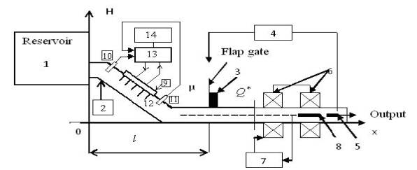 Figure 1 shows a block diagram
of the apparatus. The milk from
the dairy farms is loaded into the reservoir (1), which
trough the pipeline (2) is coming to an adjusting device (3) equipped with a system of auto regulation (4) controlled
by the speed sensor of fluid flow through the pipeline (5). Then, the milk
flows through a pair of quadrupole lenses (6), producing
a given level of magnetic
field, which is regulated by an
automatic control system (7) associated with the probe-level intensity of the magnetic field (8).
Figure 1 shows a block diagram
of the apparatus. The milk from
the dairy farms is loaded into the reservoir (1), which
trough the pipeline (2) is coming to an adjusting device (3) equipped with a system of auto regulation (4) controlled
by the speed sensor of fluid flow through the pipeline (5). Then, the milk
flows through a pair of quadrupole lenses (6), producing
a given level of magnetic
field, which is regulated by an
automatic control system (7) associated with the probe-level intensity of the magnetic field (8).
Fig. 1.
General block diagram of the apparatus
The temperature of entering product for the magnetizing milk system should be 3-4 0С. For this purpose, the used fluid control system is based on the Peltier effect. The controller is made of
flat parallel, located inside the
tube, aluminum plates (12), cooled
with a Peltier element (9), the heat from which
is given through the
radiator installed outside the
pipe (14), air-cooled. In order to maintain the temperature of
the milk in a tube in the aisles 3 ± 0,5
0С there is used an electronic control
device (13) of a temperature
sensor (10,11) which is used as a thermistor
incorporated into the scheme of the temperature controller. External heat is
blown through
the radiator air.
We propose an approach that provides a transition from hydrodynamics to the automatic control system of a flow rate of liquid.
Dynamic processes in the pipeline are characterized by two variables: by the pressure ![]() and by the flow rate
and by the flow rate ![]() ,
,
![]()
 (1)
(1)
where  ,
,  −
the relative values
of pressure
and flow, respectively,
−
the relative values
of pressure
and flow, respectively, ![]() ,
, ![]() − basic values of
− basic values of ![]() ,
, ![]() ,
, ![]() –
the speed of sound propagation in the pipeline,
–
the speed of sound propagation in the pipeline,  , g −
acceleration of gravity,
, g −
acceleration of gravity, ![]() − cross-sectional area of the pipeline.
− cross-sectional area of the pipeline.
After
the transformations we obtain the
following equation for the originals:
![]() (2)
(2)
The given equation relates the two
basic quantities ![]() and
and ![]() at the end of the pipeline with
a pressure at its beginning
at the end of the pipeline with
a pressure at its beginning ![]() .
In order to make the task definite, the equation of the flow rate
.
In order to make the task definite, the equation of the flow rate ![]() should be added to
the equation (2):
should be added to
the equation (2):
![]() (3)
(3)
The joint solution in managing (2) and (3) determines the basic values
![]() and
and ![]() at the end of the pipeline with
the definite values of the pressure
at the end of the pipeline with
the definite values of the pressure
![]() at its beginning and in the position of
the gate
at its beginning and in the position of
the gate ![]() .
.
The analysis of the equation (2) shows that the length
of the pipeline can be replaced (by
the electric model) (while
creating the automatic control systems), by the reinforcing links with
delay, and by the performing a
linearization of the equation (3), we can apply the methods of the analysis of linear systems with delay [6,7].
Therefore a block diagram of
the model is designed to determine the value ![]() and
and ![]() , in
order to determine the changes in pressure and
flow at the point
, in
order to determine the changes in pressure and
flow at the point ![]() (Fig. 2), prepared on the basis of
controls (2) and (3). To the
input there are given the proportional signals
(Fig. 2), prepared on the basis of
controls (2) and (3). To the
input there are given the proportional signals ![]()
![]() and
and ![]() ,
which passed through the model units and
converted to the desired variables
,
which passed through the model units and
converted to the desired variables ![]() and
and ![]() . Similar systems of diagnostics it is applied in work
[8].
. Similar systems of diagnostics it is applied in work
[8].
This conclusion about the possibility of unit recording with distributed parameters, functioning as a delay follows
from the physical considerations: the object with distributed parameters can be represented
as ![]() as a series-connected elementary
components of the first order, and such links can be represented as a retarded unit.
as a series-connected elementary
components of the first order, and such links can be represented as a retarded unit.
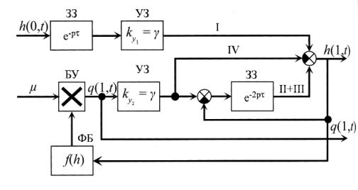
Fig. 2. The block
diagram of the model
ЗЗ- delay unit; УЗ- intensifying
unit;
БУ- multiplying unit;
ФБ-
functional unit with the input h(l,t)
and output ![]() ; I, II, III, IV- composing equations (2).
; I, II, III, IV- composing equations (2).
Because of the transcendence of the transfer
function level of delay, the characteristic equation of the closed-loop
system is also transcendental,
so the algebraic criteria for stability can not
be directly used. However, private criteria of Mikhailov and
Nyquist can be generalized for the case of delay systems, ie the system under consideration is stable [9].
For
many processes
the characteristic feature is a significant time lag response
of the object (change of the output value ![]() )
on the change of the control action
)
on the change of the control action ![]() .
According to the calculations for a
particular value of the ratio of
the delay time of the object
.
According to the calculations for a
particular value of the ratio of
the delay time of the object ![]() to its time constant
to its time constant ![]() (for instance, at
(for instance, at ![]() ) the
effectiveness of the
control laws is sharply reduced because
of the large static (P, PD-laws) or dynamic (I,
PI, PID - laws) errors, and in
some cases, the system may become unstable. Therefore there were developed special (non-classical)
laws of control: proportional-integral-differential (PIR - law) and proportional-integral of the background (PIP
- law).
In comparison with the classical control laws, using only
the information about the deviation of the controlled quantity of
a given value
) the
effectiveness of the
control laws is sharply reduced because
of the large static (P, PD-laws) or dynamic (I,
PI, PID - laws) errors, and in
some cases, the system may become unstable. Therefore there were developed special (non-classical)
laws of control: proportional-integral-differential (PIR - law) and proportional-integral of the background (PIP
- law).
In comparison with the classical control laws, using only
the information about the deviation of the controlled quantity of
a given value
![]()
![]() , here is used a priori information about
the controlled object on the basis of which the classical control
law is exists
, here is used a priori information about
the controlled object on the basis of which the classical control
law is exists
 ,
,
where ![]() - coefficient
of proportionality (transfer) in order to make certain corrections. In the case of a parallel transfer the correction function of the
adjusted control law
- coefficient
of proportionality (transfer) in order to make certain corrections. In the case of a parallel transfer the correction function of the
adjusted control law ![]() can be written as
can be written as
![]() (4)
(4)
where ![]()
![]() – transfer functions of the base-level control
and correction unit.
– transfer functions of the base-level control
and correction unit.
In connection with the above-described process the control block diagram of the control panel-controller can be represented as it is given in Figure 3.
The analysis of this scheme shows that
the control action is formed as
the algebraic sum of two components: ![]() -
component on the output of PI − regulator;
-
component on the output of PI − regulator; ![]() - component unit of a parallel correction. The introduction of the component
- component unit of a parallel correction. The introduction of the component ![]() weakens
the proportional and integral
part of the basic component (
weakens
the proportional and integral
part of the basic component (![]() and
and ![]() are less than one) at
are less than one) at ![]() . The latter condition is ensured by the
introduction of level 4, which is a model of controlled
object. Therefore, the PIP
- the regulator provides a high level
of control action
. The latter condition is ensured by the
introduction of level 4, which is a model of controlled
object. Therefore, the PIP
- the regulator provides a high level
of control action ![]() at
at ![]() and gradual decline of this level at
and gradual decline of this level at ![]()
![]() .
.
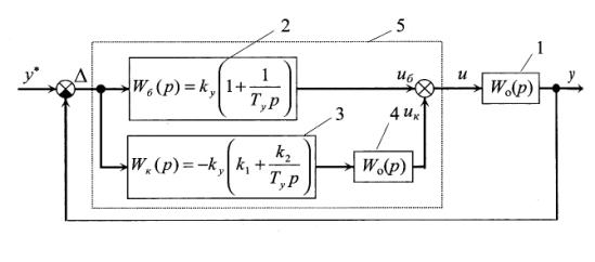
Fig. 3. Block diagram of automated control panel with PIP system:
1- control panel;
2- PI-regulator; 3,4- correction
units; 5- PIP- regulator.
As in the case with the PIR -
regulator, the implementation of PIP
- control law improves
the quality of transient stability
process and increases the stability in amplitude and
phase compared with PI-regulator.
Beside this, the parameter settings of
the correction level ![]() and
and ![]() because of their connection with linear proportional and integral components of the
output signal correction level
3, is quite
simple.
because of their connection with linear proportional and integral components of the
output signal correction level
3, is quite
simple.
Therefore, the introduction of delayed units
of the structure of parallel
correction unit can significantly improve the quality of transient processes in
the ACS objects with a significant delay, as in the system of milk magnetization.
Literatura
1. Miroshnik I. V. Teorija avtomaticheskogo upravlenija. Linejnye
sistemy. SPb, Piter 2005.
2. Vlasov K. P. Teorija avtomaticheskogo upravlenija. Uchebnoe posobie. H,
Izd-vo Gumanitarnyj centr 2007.
3. Aleksandrov A. G. Optimal'nye i adaptivnye sistemy. M, Vysshaja
shkola 1989.
4. Fradkov A. L. Adaptivnoe upravlenie v sozhnyh sistemah. M, Nauka
1990.
5. Voronin A. M. , Aldibekova A. N.
O stabilizacii magnitnyh polej
jelektro-fizicheskih ustanovok s ispol'zovaniem JaMR. Vestnik Nacional'noj Inzhenernoj
Akademii RK 2/2012, s. 89-94.
006. Makarova I.M., Lohchena V.M. Intelektual'nye sistemy
avtomaticheskogo upravlenija. M,Fizmatgiz 2001.
7. Popov E. P. Teorija linejnyh sistem avtomaticheskogo regulirovanija
i upravlenija. M, Nauka 1989.
8. Sulejmenov B.A., Shuvatov T.T. Metodika postroenija sistemy
diagnostiki GPA. № 4 (30), Inzhenerno tehnicheskij zhurnal «Vestnik
avtomatizacii», 12/ 2010, s. 7-9.
9. Syzdykov D.Zh., Shirjaeva O.I., Omirbekova Zh.Zh. Razvitie metoda
obwego parametra dlja immunnoj modeli. Inzhenerno tehnicheskij zhurnal «Vestnik
avtomatizacii», № 3 (25), 9/ 2009, s. 31-33.