New Catalytic Conversion
of Hydrocarbons in a Heated Tube at a Nearly Stoichiometric Vapor to Gas Ratio
Joint
Institute of High Temperatures, Russian Academy of Sciences, Moscow, 125412
Russia
Moscow, 125412,
Izhorskaya st., 13/19, e-mail:
vsigumnov&mail.ru
(Россия 125412, Москва, ул.
Ижорская, д.13/19, Объединенный институт высоких температур РАН, Канцелярия)
Abstract—A method for the catalytic vapor and carbon dioxide conversion of hydrocarbons is suggested. The conversion was performed in heated tubes at a nearly stoichiometric vapor-to-gas ratio. The energy intensity of the process and the rate of oxidants (H20 and/or C02) thus decreased, while the lifetime of the catalyst increases. An inert Zr02 packing (inhibitor) was used. It was the first to be loaded into the tube along the gas pathway and then alternated with the catalyst. In a layer of inert inhibitor, the gas reaction mixture was heated to a temperature close to that of the tube wall. The catalyst was then fed in, providing additional heat to the catalytic packing layer for endothermal conversion. The catalyst carbonization was thus reduced. The number of layer pairs was calculated with allowance for the consumption of the processed products and the tube size in industrial pipe furnaces. The proposed conversion procedure was tested in the laboratory and on pilot plants and then in the industrial pipe furnaces of the coke gasworks of PO Angarsknefteorgsintez, the Novocherkassk Plant of Synthetic Products (NPSP), and the Oskol Electrometallurgical Industrial Complex (OEIC).
Keywords:
methane, natural gas, hydrocarbons, hydrogen, carbon, carbon oxide, nickel
catalyst, inhibitor, heated tube, endothermal reaction, catalytic conversion.
INTRODUCTION
The catalytic vapor and carbon dioxide conversion of hydrocarbons in heated tubes is the main procedure for producing the 0/H2 gas mixture used as industrial and reductive gases and as syngas. Conversion of hydrocarbons is the main and at the same time most energy intensive process in nitrogen chemistry, polymer production, and direct iron reduction in metallurgy. It is, therefore, one of the major challenges in upgrading these industries and analyzing the neck stages in technology remodeling. The catalytic vapor and carbon dioxide conversions of hydrocarbons are represented by the following chemical reactions:
Cn Hm + nН20 = nСО +
(n + т/2)H2, (1)
Cn Hm + nC02 = 2nCO +
(w/2)H2. (2)
The industrial processes are generally performed in reaction mixtures with a large (fourfold or higher) excess of an oxidant at 900—1200 К and at pressures from 0.2 to 4 MPa to avoid catalyst carbonization. A stoichiometric catalytic conversion is difficult to perform in industry. This problem can be solved, for example, by modifying the structure of the tube reactor, supplying additional heat in the catalyst bed [ 1 ] for endothermal reactions (1) and (2), and reducing carbon deposition in the catalyst pores.
The industrial processes are generally performed in reaction mixtures with a large (fourfold or higher) excess of an oxidant at 900—1200 К and at pressures from 0.2 to 4 MPa to avoid catalyst carbonization. A stoichiometric catalytic conversion is difficult to perform in industry. This problem can be solved, for example, by modifying the structure of the tube reactor, supplying additional heat in the catalyst bed [ 1 ] for endothermal reactions (1) and (2), and reducing carbon deposition in the catalyst pores.
A reaction mixture is fed into a heated tube at T ~ 700 Kat the inlet (the temperature at the outlet is 1200 K).
According to our calculations of the thermodynamic probability of carbon deposition, carbon is not deposited in vapor conversion under these conditions when the H20/CH4 molar ratio is higher than 1.5 [2]. Reactions (1) and (2) with methane occur according to the schemes [3]
CH4 + H20 + 204 kJ/mol = CO + 3H2, (3)
CH4 + C02 + 248 kJ/mol = 2CO + 2H2. (4)
These reactions are highly endothermal (for purposes of comparison, water evaporation requires 41 kJ/mol). Under catalytic conversion conditions, carbon is mainly formed by the reactions
CH4 + 78 kJ/mol = С + 2H2, (5)
Carbon is further oxidized by the reactions
С + H20 + 118 kJ/mol = CO + H2. (7) С + CO, + 161
kJ/mol = 2CO. (8)
All these reactions are energy intensive. Direct reactions
(3) and (4) are unlikely to occur at T < 1200 К because the CH4,
H20, and C02 molecules must have an energy of more than
2.5 eV. There are up to 0.001% such molecules in the energy
distribution. The estimated probability of their meeting is up to 0.01, and
carbon will not be isolated in the catalyst if the conditions of heat transfer
from the tube wall to the catalyst bed provide heat for reactions (7) and (8).
If C02 and
|
Fig. 1.
Dependence of the effective latent heat of reaction on the excess of oxidants
n. |
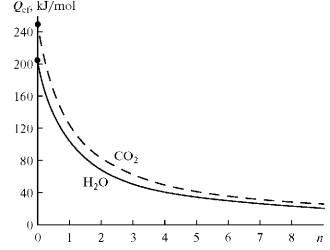
H2O are added in excess over stoichiometry in (3) and (4),
the heat effect of the reactions will decrease exponentially [4—6]. This
dependence was called the effective latent heat of reaction [6]:
![]()
![]()
![]()
![]() (9)
(9)
Here, ∆H is the standard thermal effect of the
reaction under study, and n is the number of moles of
all gases in the reaction gas mixture in the left part of the equations,
ignoring the moles of gases that provide the stoichiometry; k -
coefficient f ( C i ). Figure 1 shows dependences (9) for
the reactions
CH4 + H2O + n H2O
= CO + 3H2 + nH2O, (10)
CH4 + CO2 + n CO2
= 2CO + 2H2 + n CO2, (11)
where
n = 1 and Qef = 102 kJ/mol if H2O/CH4
= 2.
At n > 1.5 the reaction
CH4 + 2H2O = CO2 + 4H2 (12)
will be pronounced. The total excess of H2O
reacts with the produced CO:
H2O + CO = H2 + CO2. (13)
When over 50% of CH4 has reacted, parallel
reactions start that are the reverse of (7) and (8) and liberate carbon:
CO + H2 = C + H2O, (14)
2CO = C + CO2. (15)
The
conversion is catalyzed almost completely in the catalyst pores, where carbon
nanostructures appear in the form of fullerenes and carbon filaments [5, 6].
The carbon nanostructures increase the active contact surface manyfold.
Reactions (7) and (8) with carbon require that the CO2 and H2O
oxidant molecules have an energy of at least 1.67 and 1.22 eV,
respectively. The higher the H2O(CO2)/CH4
ratio, the larger the number of oxidant molecules having these amounts of
energy. This is numerically expressed as a decrease in the effective latent
heat of the reaction. Equation (1) defines (in general form) the dependence of
the energy distribution of oxidant molecules, the probabilities of
intermolecular collisions, and the densities of molecules and the molecular
diffusion in the catalyst pores.
EXPERIMENTAL
A unit for studying the conversion of hydrocarbons
(including those with stoichiometric ratios of components) on a catalyst in a
heated tube was created at the Joint Institute for High Temperatures, Russian
Academy of Sciences [2]. In the experiments described in this work, we used
catalysts with known physicochem- ical and hydrodynamic properties of the
catalyst bed (GIAP-16 and GIAP-8). Similar results can be obtained for any
modern catalyst. The test tube of corrosion-proof steel was 60 mm in diameter
and 1.5 m in length; the wall thickness was 3 mm. For GIAP-16, we used Raschig
rings 15 x 12 x 7 mm in size; the NiO concentration was 26 wt %, porosity 35.5
vol %; resistance 70 MPa. ZrO2 balls with a diameter of 21 mm and a
strength of 140 MPa were used as an inhibitor. Uniform heating of the wall to
1400 K was possible due to the direct electrical heating of the tube. The wall
temperature (Tw) was measured along
with the average gas temperature at the inlet and outlet, the temperature
along the tube and its radius (T), and the reaction gas
concentrations on and along the tube axis and near the wall. The adjusted
parameters were the rate and composition of gases at the inlet of the tube, the
pressure in the reactor, the heat flux from the tube wall, the temperature of
reaction gases at the outlet of the tube, and the H2O(CO2)/CH4
ratio. A detailed description of the measurement procedure and the scheme of
the experimental unit are presented in [2].
Figure 2
shows a heated tube filled with a continuous layer of GIAP-16 catalyst, as in
the case of industrial conditions. The GIAP-16 charge was 3.6 x 10⁻³
m3. In the experiments, the methane flow rate was (0.1—0.32 x 10⁻³)
nm3/s; the heat flow rate was 10—35 kW/m2; and the
pressure in the reactor was 50—100 kPa.
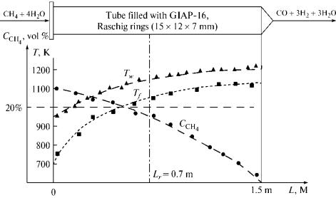
Fig.
2. Variation in the
reactant gas temperature Tf, wall temperature Tw, and methane concentration CCH4 along a tube without carbon
deposits.
Steady conversion was observed at H2O/CH4
> 4 (at H2O/CH4 < 4, steady conversion could not be
achieved without carbon liberation). Figure 2 shows the characteristic
experimental data. The active reaction zone lies on a segment of ±0.1 m in the
vicinity of the section Lr. The radial temperature distribution
on a segment of section Lr in the tube is presented in Fig. 3.
According to these parameters, the converted gas contained at least 40 vol %
oxidants at the outlet of the tube, which is not. acceptable for the reduction
of iron oxides.
A scheme for the catalytic conversion of methane in a heated tube was proposed based on the results and using the calculations in [2]. The liberation of carbon was attributed to a lack of heat in the heated tube. We used overheating of the reaction mixture on an inhibiting packing separated into two layers for an additional heat supply. A layer of inert inhibitor on which there was no catalytic conversion was placed at the inlet of the tube. According to Fig. 4, the layer was 0.46 m in length and consisted of ZrO2 balls with a diameter of 21 mm; the the charge was 1.2 dm3. The experimental data on the inhibiting properties of ZrO2 are given in [8].
The next layer was the GIAP-16 catalyst (charge, 2.4 dm3).
In the first layer, methane did not react and did not decompose with the
liberation of carbon, but was only heated to a temperature close to that of the
wall. The inert ZrO2 support was chosen based on comparative
experiments with substances used as catalyst supports [7—9]. The experiments
with the inhibitor layer were performed under conditions similar to those of
the experiment illustrated in Fig. 2. They started at H2O(CO2)/CH4
= 3 and continued until the H2O(CO2)/CH4 ratio
gradually approached a stoichiometric ratio of 1. The appearance of carbon
deposits and, as a consequence, catalyst decomposition were determined from the
pressure differential at the inlet and outlet of the heated tube and along the
catalyst bed. The increase in the pressure differential on a specific segment
corresponded to the zone of the most active liberation of carbon. The pressure
differential increased as carbon was deposited and the catalyst decomposed.
Fig. 3. Temperature distribution within the radius of a tube
on segment L, calculated using the quasihomogeneous model (A,ef = 3
W (m K)). For parameters, see Fig. 2.
A steady technological mode of catalytic conversion was attained at an
oxidant to methane ratio of 1. Figure 4 shows the characteristic change in the
tube wall and reactant gas temperatures. The reaction mixture on ZrO2
balls at the inlet was heated to a temperature close to that of the wall. As
can be seen in Fig. 4, the methane concentration remained constant.
According to the chromatographic analysis data, hydrogen and carbon oxide did
not form in the ZrO2 packing. An active reaction occurred when the
gases reached the catalyst bed. The energy stored in the course of heating on
ZrO2 was sufficient for reactions (3) and (4) to occur without
carbon liberation. As the heat was spent on the reaction, the reactant gas temperature
in the catalyst bed reached its minimum (Tmin), which is the
function of all main parameters of the conversion. The segment between the
inhibitor- catalyst (IN-CA) boundary and the extreme temperature of reactant
gases in the catalytic packing layer corresponded to the most active reaction
zone (2) (MARZ-2). The segment from IN—CA to the cross section
where up to 50% of the initial amount of methane reacted was the most active
reaction zone (1) (MARZ-1). If Tmin falls to a certain value (TminCR),
MARZ-1 and MARZ-2 do not coincide, and the difference between their linear
sizes equals the active carbon deposition zone (ACDZ).
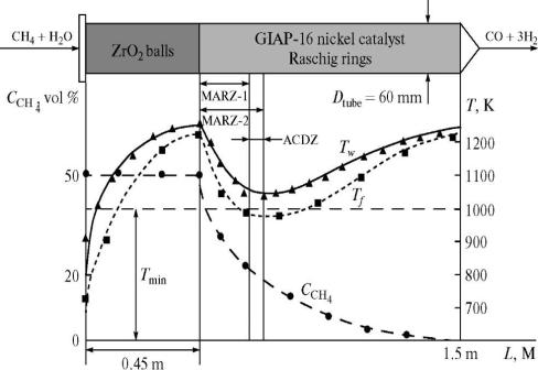
|
Fig. 4. Distributions of the wall (Tw)
and reactant gas (Tf) temperatures and methane
concentration along the tube. MARZ-1, MARZ-2, and ACDZ are the most active
zones of reactions (1) and (2) and the active carbon
deposition zone, respectively. For the parameters of the experiment, see Fig.
2. |
Based on the laboratory experiments and
calculations using the quasihomogeneous model
with the ideal ousting
[10] (the notion of effective heat conductivity was used for calculating the
heat transfer), we proposed a scheme for the catalytic conversion of
hydrocarbons in a heated tube with intermediate overheating on inhibiting
packings, which was first considered in a different formulation in [12]. In
industry, this technique was first tested on the pilot unit of the
Novocherkassk Synthetic Products Plant (NSPP). The scheme for the charging of
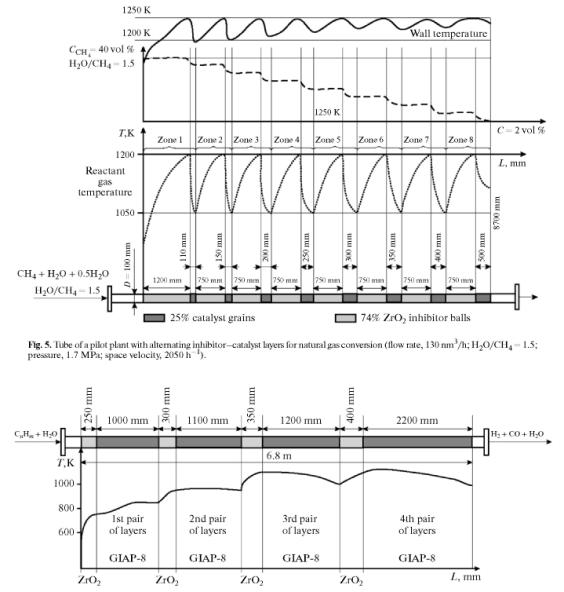
the tube being tested is presented in Fig. 5. The length of the catalyst bed
was calculated under the condition that the reduction in the temperature of the
catalyst bed be no more than 150 K. The length of the heated tube of the
industrial furnace was 11 m, the outer diameter 120 mm, and the length of the
illuminated part of the furnace 8.7 m.
The temperature range of reactant gas heating in the pilot plant was
set based on the heating conditions and technical specifications for tube
operation. The working rate of methane for conversion was 80 nm3/h
at H2O/CH4 = 1.5. The sizes of the inhibitor layer and
catalyst bed were calculated from these conditions using the heat transfer
conditions and the ideal ousting model. The calculations gave eight
inhibitor—catalyst layer pairs in the given mode at a methane rate of 130 nm3/h
and H2O/CH4 = 1.5. The average pressure in the tube was
1.7 MPa; the residual methane content was 11 vol %, which is close to the
equilibrium methane content under the given test conditions. The space
velocity of methane was 2050 h-1 under the normal conditions. The
operation time of the tube under the chosen test conditions was 4 days, after
which the initial properties of the catalyst according the technical
specifications did not change.
Industrial trials of the catalytic conversion of Cj—C5
refinery gases in the intermediate heating mode. The trials were carried out in the coke gasworks of
PO Angarsknefteorgsintez. The refinery gas was a mixture of hydrogen (up to 30
vol %) and a wide fraction of C1-C5 hydrocarbons (mainly
propane and butane). Conversion was performed with a water vapor at H2O/C
= 5 in a pipe furnace containing 72 pipes with an illuminated part of 6.8 m and
an inner diameter of 158 mm. The GIAP-8 catalyst in the form of cylinders was
used; the cylinder height was 16 mm, diameter 14mm, 7.5 wt % NiO, porosity 54.5
vol %, stability 25 MPa. The inhibitor were ZrO2 balls 21 mm in
diameter used as a packing for high-temperature heat regenerators. The run
duration of the furnace before the catalyst reloading was 10-15 months. After
months, the catalyst was carbonized and half decomposed in the furnace. It was
discharged and forwarded for recycling.
|
Fig. 6. Location of packings and variation in reactant gas temperature along a tube with an inner diameter of 158 mm for vapor conversion of C1—C5 hydrocarbons (ZrO2 balls with a diameter of 21 mm; GIAP-8 catalyst; cylinders with a diameter of 14 mm and a height of 6 mm). |
Oil
gas hydrocarbons generally quickly carbonize the catalyst in the temperature
mode of the catalytic conversion of natural gas. The temperature mode of the
pipe furnace, therefore, had a reaction gas temperature 670 K at the inlet and
1070 K at the outlet. Higher hydrocarbons relative to methane decompose to
carbon by a number of chemical schemes [11]. An estimation of the thermodynamic
probability of carbon formation shows that the majority of hydrocarbons
decompose according to a conventional scheme [12]
C5H12 → C2H6
→ C2H4 → C2H2 → CH4 → C (16)
The scheme can be more complex. The
thermody- namic analysis of the equilibrium states was rough. The reaction rate
of a chemical transformation to carbon depends on the transfer conditions in
the catalyst bed. The rates of hydrocarbon transformations were adjusted using
intermediate overheating of reactant gases with an inhibitor. The use of the
inhibitor allowed us to set the requited temperature mode and increase heat
supply to the reaction zone.
Figure
6 shows the arrangement of packings and the variation in the temperature of
reactant gases along the tube (the packing layer sizes are indicated). The ZrO2
inhibitor balls were placed at the inlet of the
tube, and the reaction gas mixture was heated in a relatively short layer of
1.5 size. A long (12-size, as in Fig. 5) inhibitor layer cannot be placed here
because higher hydrocarbon molecules decompose to carbon and hydrogen at T
> 750 K according to scheme (11). In a small (up to double sized) layer, the
decomposition of heavy hydrocarbons occurs according to schemes similar to
(12). The hydrocarbons then react only slightly with H2O in the
catalyst bed. Hydrogen is formed in this layer and retards the formation of
carbon [3]. At the outlet of the catalyst in the first pair of
inhibitor—catalyst layers, the reaction gas no longer contains the C5
and C4 fractions and can therefore be heated to 950 K. In the second
pair of layers, full conversion ofC3 and C2 hydrocarbons
occurs. This is why the gas is heated to 1100 K in the third pair of layers
[8], the most active conversion stage starts [7], and the temperature falls to
a dangerous level. In the fourth pair oflayers, the hydrocarbons are fully
converted to compounds whose composition meets the conditions and input
parameters of the general process [7]. The inlet and outlet temperatures (Fig.
6) and the wall temperature were measured, and the intermediate temperatures
were calculated.
The pipe furnace was
stopped after 15 months of operation because of the catalyst decomposition in
the majority of tubes. The catalyst was half destroyed in the main pipes but
remained in its initial state in the tested pipes; the inhibitor did not change
and could be recycled. The main results of full-scale industrial trials were
described in [13, 14].
CONCLUSIONS
We
have presented the results from our laboratory experiments and industrial
trials of hydrocarbon conversion in tubes with intermediate overheating of
reactant gases in an inhibitor—catalyst system and the calculated data. All of
the trials (carried out at the NSPP, PO Angar- sknefteorgsintez coke gasworks,
and OEIC) were recognized as successful and promising. The laboratory trials
showed that stoichiometric conversion of methane with water vapor, carbon
dioxide, and their mixtures was possible without carbon isolation and hence
catalyst decomposition. The inhibiting packing in industrial pipe furnaces
was found to prolong the catalyst's service life. For precise calculations of
the size of the inhibitor—catalyst layers and their number in the reactor pipe,
we recommend using the effective latent heat ofreaction Qef, which
is a precise characteristic of the heat flows responsible for the endothermal
reactions in the catalyst bed. Our main conclusion: The intermediate
overheating of a reaction mixture on an inhibitor in the catalytic conversion
of hydrocarbons in a pipe reactor allows the temperature profile to be smoothed
along the pipe radius in the catalyst bed, increasing the heat supply to the
reaction zone and hence the reactor output and the catalyst service life. This
is especially important if tubes with larger diameters and hydrocarbons heavier
than methane are used. Tubes with larger diameters and natural gas with lower
methane contents are planned for use in pipe reactors (reformers) at OEIC. A
program of trials has been developed for this purpose under the supervision of
the Joint Institute for High Temperatures, Russian Academy of Sciences.
REFERENCES
1. Igumnov, VS. and Vizel', Ya.M., Pretsizionnaya katali- ticheskaya
konversiya uglevodorodov dlya pitaniya tverdo- oksidnykh toplivnykh elementov:
Mater. VIIMezhdunarod- nogo foruma "Vysokie tekhnologii XXI veka" (Precision Catalytic Conversion of
Hydrocarbons for Supply of Solid Oxide Fuel Cells, Proc. 7th Int. Forum
"High Technologies in the 21st Century"), Moscow, 2007.
2.
Igumnov,
VS., Cand. Sc.
(Eng.) Dissertation:
MIKhM, 1989.
3. Spravochnik azotchika:
Fiziko-khimicheskie svoistva gazov i zhidkostei. Proizvodstvo
tekhnologicheskikh gazov. Sintez ammiaka. (Nitrogen Chemist's Handbook: Physicochemical
Properties of Gases and Liquids. Production of Industrial Gases. Synthesis of
Ammonia), Moscow: Khimiya, 1986, vol. 1.
4.
Igumnov,
V.S., Technical and
Technological Methods of Realization of Steam Catalytic Conversion of Natural
Gas with a Methane—Water Proportion Close to Stoichiomet- ric Ratio, in Hydrogen Materials Science and
Chemistry of Carbon Nanomaterial, NATO Security Science Series A: Chemistry
and Biology, The NATO Program for Security Through Science, 2007, p. 555.
5. Igumnov, VS., Statistical Weight of
Formation Fullerene in Conditions Catalytic Interactions of Methane with Water
the Ferry,
Conference ICHMS,
2005.
6.
Igumnov,
V.S., Carbon Nanostructure: An Intermediate Stage in Catalytic Conversion of
Methane, 3rd Int.
Symp. "Fullerene and Fullerenoid Structures in the Condensed
Environments",
Minsk, 2004.
7. Vizel', Ya.M., Doctoral (Eng.) Dissertation, St. Petersburg: Tekhnol. Institute,
1993.
8. Vizel', Ya.M. and Igumnov, V.S., Teplofiz. Vys. Temp., 1983, vol. 21, no. 3.
9.
USSR
Inventor's Certificate 1308648, 1985.
10. Mostinskii, I.L., Igumnov, VS., Vizel',
Ya.M., and Zyry- anov, S.I., in Atomno-vodorodnaya energetika i tekh- nologiya. Sb.
st. Vyp. 8 (Atomic
Hydrogen Energetics, ACollection of Papers), no. 8, Moscow: Atomizdat, 1988.
11. Tesner, P.A., Obrazovanie ugleroda iz uglevodorodoi
gazovoi fazy
(Carbon Formation from a Hydrocarbon Gas Phase), Moscow: Khimiya, 1972.
12. US Patent 3617227, 1971.
13. USSR Inventor's Certificate 1829181,
1989.