Васильева Ю. З.
Национальный исследовательский Томский политехнический
университет
Designing of digital band-pass filter for
synchronous generator diagnostic system
The necessity of developing digital band-pass filter at creation of synchronous generator diagnostic system of turn-to-turn
short circuit rotor winding, based on
the harmonic component separation from the signal obtained in the output of the
magnetic field sensor [1]. A problem complexity is the low value of the
intelligence signal - 1.5 ... 3% of the fundamental harmonic, and it is also a large
number of noise (pulse noises, higher harmonic components, etc.) [2].
Statement of
objectives: to develop the minimal order digital band-pass filter capable of
suppressing constant and higher harmonic components, pass and amplify the
signal with frequency equal to the rotor frequency.
There was a problem to dedicate the signal being proportional to the
value of sinusoidal half-waves asymmetry
during the diagnostic system development.
For example, Figure 1 shows a perfect EMF signal from the sensor output.
The signal asymmetry is manifested in
the decreasing of the one of the 2p
half-waves amplitude (∆е) (Figure 1, p = 1), where p is machine pole pairs number.
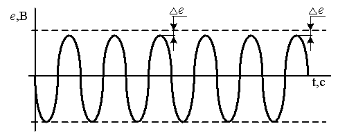
Figure
1. The sensor signal data in case of a SG damage
The problem was solved by EMF converting into a unipolar signal,
followed by the band-pass dedicating of the
subharmonic frequency f1=fs/p, where fs is
the network frequency. The digital band-pass filter (BPF) consisting of the high pass filter (HPF) and
low pass filter (LPF) is necessary to dedicate the
subharmonic frequency f1.
The level of the BPF useful signal increases with increasing LPF order,
the filter response time also increases. It has a negative impact on the device
operating speed.
Special requirements to the HPF order was not made in the PS
development. The smallest filter order N was the choice criterion for required
level of noise suppression.
The required level is determined by the ratio of useful signal level to
general signal level:
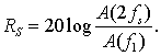
The calculation showed that the required attenuation level was equal 60
dB at the minimum level of the selected signal was 1.5% of the total.
The Chebyshev filter, Butterworth and elliptic filters were selected as
the LPF basis. The each selected filter order was calculated according to the
formulas (1), (2), (3) at the suppression level RS = 60 dB [3,4].
The Butterworth filter order
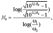 (1)
(1)
The Chebyshev filter order
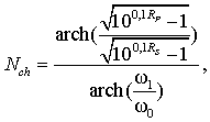 (2)
(2)
The Cauer filter order
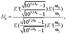 (3)
(3)
where, Nb, Nch,
Nk – are Chebyshev, Butterworth and elliptic filters orders, RP – is the signal distortion
level in the pass-band, RS
–is the noise suppression level, ω0– is a passband, ω1 – is a
rejection frequency, К – is a
complete elliptic integral, ![]() – is a complementary
elliptic integral.
– is a complementary
elliptic integral.
The dependence of the filters order from the useful signal level Δe at the given
suppression level is shown in Figure 2.
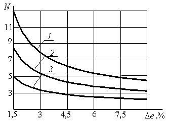
Figure 2. The dependence of
the filters order from the useful signal
level Δe at RS = 60 dB
(1 - by Butterworth 2 - by Chebyshev, 3 - by Cauer)
As evident from the figure 2, the
minimum order value Nk of
elliptic filter is equal to 5 in case of RS=60
dB and Δe =1,5 % . The BPF was implemented
based on the elliptic filter. A distortion of the useful signal in the passband
amounted to
0.5 dB.
The BPF
consists of the high-pass and low-pass filter component, which can be
represented as the following transfer function:
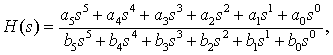
where H(s)
is the transfer function, s is the complex variable, ai,bi
are the transfer function coefficients. The BPF transfer function coefficients
values for the above example are shown in Table 1.
Table 1. The BPF coefficients
|
LPF |
a0 |
a1 |
a2 |
a3 |
a4 |
a5 |
|
7,994·1011 |
0 |
3,168·106 |
0 |
2,62 |
0 |
|
|
b0 |
b1 |
b2 |
b3 |
b4 |
b5 |
|
|
7,988·1011 |
9,204·109 |
4,652·107 |
2,08·105 |
376,5 |
1 |
|
|
HPF |
a0 |
a1 |
a2 |
a3 |
a4 |
a5 |
|
0 |
3,101·108 |
0 |
3,852·104 |
0 |
1 |
|
|
b0 |
b1 |
b2 |
b3 |
b4 |
b5 |
|
|
1,168·1013 |
4,457·1010 |
2,497·108 |
5,66·104 |
1,136·103 |
1 |
The BPF experimental test was carried out on synchronous generator
GAB-4-T/230 at the laboratory. Filter
characteristics coincided with the calculated values. It has allowed to reveal reliably
not less than 2% of short circuits in generator various operating modes.
Сonclusions
1. The designed filter
fully meets the requirements of the synchronous generator diagnostic system;
2. The band-pass
filter designing method is justified for synchronous generator diagnostic
system;
3. The efficiency of
operation designed filter is experimentally confirmed.
The
list of references:
1. Gutnikov V.S.
Filtraciya izmeritelnyh signalov [Filtration of measuring signals]. – L.:
Energoatomizdat, – 1992. – 192p.
2.
Polishсhuk V.I., Novozhilov A.N.
Ustrojstvo zashchity sinhronnoj elektricheskoj mashiny ot vitkovyh i dvojnyh na
zemlyu zamykanij v obmotke rotora [Protection device of synchronous electric
machine against turn-to-turn and double earth fault in the rotor
winding]//Patent № 22450 (KZ). Official
bulletin. Prom . Property. 2010, no. 4.
3.
Polishchuk V.I. Postroenie zashchity ot vitkovogo zamykaniya v obmotke
rotora sinkhronnogo generatora na osnove induktsion-nogo datchika magnitnogo
polya rasseyaniya [Construction of protection interturn fault in the winding of
synchronous generator rotor based on inductive sensor magnetic stray field]. Bulletin of the Tomsk Polytechnic University, 2012,
vol. 321, no. 4, pp. 57-61.
4. J. D. Rhodes
Teoriya elektricheskih filtrov [Theory of Electrical Filters]. – M.: Sov.
radio, – 1980. – 240p.