Prof. Bezvesilnaya
E.N., postgraduate student Tkachuk A.G.
National technical university of Ukraine “Kyiv Polytechnic Institute”,
Zhytomyr State
Technological University, Ukraine
LASER ANGLE MEASURING INSTRUMENTS
With a
help of a laser gyro such instruments as goniometers, devices for measurement
of the glass refractive index, geodesic and astronomical angle measuring
devices and other can be developed. The utilization of laser gyro in angle
measuring instruments allows to increase the accuracy, reliability and
measurement reproducibility, to decrease the time of measurements, to automate
the process of angle measurements.
The
scheme of goniometer on laser gyro base and its operation algorithms are presented.
Mathematical model for an angle measurement error is also presented. The
analysis of measurement error components has been carried out. We paid special
attention to the effect of the Earth's angular rate on the angle measurement
error and showed the ways for reduction of this component of the error.
International comparisons results are presented as wed.
Implementation
of laser gyros in angle measuring instruments allows to increase the accuracy,
reliability, and measurement reproducibility, to considerably decrease the time
of measurements, to automate the process of angle measurement.
The
first experimental goniometer on laser gyro (LG) base was designed at the D.I.
Mendeleyev Institute for Metrology (St. Petersburg, Russia). The first
commercial angle measuring instrument on LG base was produced in the early
1980s by the Arsenal plant (Kiev, Ukraine). It is the goniometer-spectrometer
GS1L that is being produced on commercial basis and exploited at many plants
in Ukraine and abroad. The commercial laser goniometer system EUP-1L is
designed by the St. Petersburg Etectrotechnical University
The
simplified scheme of the goniometer on LG base is given in the figure 1. On rotating
device 1 are mounted: object table 2, prism 3 under check, the angles of which
are to be measured, laser gyro 4. Rotating device 1 rotates with a constant
speed with the aid of electric motor 5 controlled by electric drive unit 6.
Close to table 2 mounted is photoelectrical slit autocollimator 7. During
rotation of rotating device 1 with prism 3 the electrical pulses are received
from each face of the prism at the autocollimator output. From the base face
tie unit 8 the signal of selection of the first prism face is received. With
the aid of this signal the control unit 9 selects the autocollimator pulse from
the first face of prism 3. This pulse actuates pulse counter 11 which begins
counting the number of signal periods of laser gyro 4. The counter 11 is
stopped by autocollimator 7 pulse received from the second prism face and
finishes counting the number of signal periods of laser gyro 4 while the
counter 12 begins counting. With coming of autocollimator 7 pulse from the
next prism 3 face, one counter turns on while another turns off. The
information from counters 11 and 12 is transmitted to computer 14 with the aid
of communication device 13.
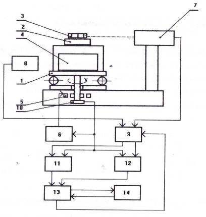
Fig. 1 The scheme of goniometer on laser gyro base
Thus
the numbers received by computer within one full turn of rotating device 1 are
as follows:
from
counter 11: from counter 12:
 (1)
(1)
… …
where t1, t 2, t 3,...,
tn, t n+1 is
the time of autocollimator pulse coming
from the first, second, third, etc.
prism faces and then again from the first prism face; ![]() is the frequency at the output
of laser gyro; n is the
number of faces of the prism under check.
is the frequency at the output
of laser gyro; n is the
number of faces of the prism under check.
The
checked angles are calculated by the computer from a formula:
![]()
![]() when
when ![]() (2)
(2)
where i is the number of the checked angle.
As the
principals of designing of angle converters on LG base considerably differ than
that of principals for other types of converters of similar assigning, the
sources of their errors is considerably differ as well. Therefore, experience
of evaluation of the error for conventional angle converters in this case is
not always applicable.
The
angle measurement error of goniometer on LG base can be presented by the
equation:
 (3)
(3)
where t1,
tj, t2p, are the moments (fixed
by autocollimator) of the beginning of measurement, turning to the checked
angle j<p and the angle 2p respectively; K(t)
is the laser gyro scale factor; ![]() is an angular rate of rotating device turn; a(t) is the angle
between rotation axis and sensitivity axis of laser gyro;
is an angular rate of rotating device turn; a(t) is the angle
between rotation axis and sensitivity axis of laser gyro; ![]() ,
, ![]() is the nonlinearity and zero bias of laser gyro
output characteristic respectively; Nq1, Nq2 is the noise and quantization
discreteness of laser gyro signal;
is the nonlinearity and zero bias of laser gyro
output characteristic respectively; Nq1, Nq2 is the noise and quantization
discreteness of laser gyro signal; ![]() is the calculation error; j is the real angle value.
is the calculation error; j is the real angle value.
Evaluation
of ![]() in according to formula (3) in
general is a very complicated mathematical assignment.
in according to formula (3) in
general is a very complicated mathematical assignment.
To
solve the practical tasks it is necessary to use the characteristics of
specific types of the rotating device, autocollimator, laser gyro and other
subsystems that are used in goniometers. This considerably simplifies a
problem statement.
Time of
beginning (or termination) of an angle reading can be written as a random
value:
![]() (4)
(4)
where ![]() is the exact time of forming of
pulses for counters' control;
is the exact time of forming of
pulses for counters' control; ![]() ,
, ![]() are determinated and random
components of the error respectively.
are determinated and random
components of the error respectively.
As a LG
is an angular rate transducer in inertial space, the entire instrument is
exposed to various types of the angular rates including angular rates of
rotating device (![]() ), the Earth (
), the Earth (![]() ) and the base of rotating
device in relation to the Earth (
) and the base of rotating
device in relation to the Earth (![]() ). Thus a LG is exposed to the
angular rate:
). Thus a LG is exposed to the
angular rate:
![]() (5)
(5)
In its
turn, the angular rate of rotating device in general can be represented by the formula
![]() (6)
(6)
where c is the unit vector; ![]() is the constant component of the angular rate;
is the constant component of the angular rate; ![]() is the coefficient of linear drift;
is the coefficient of linear drift; ![]() is the determinated component of angular rate (for instance, sine wave oscillations);
is the determinated component of angular rate (for instance, sine wave oscillations); ![]() is the random component of angular rate (random process);
is the random component of angular rate (random process); ![]() is the variation of angular rate each time the
device goes operational (random value).
is the variation of angular rate each time the
device goes operational (random value).
Angle
between rotation axis and sensitivity axis of laser gyro can be represented by
the formula:
![]() (7)
(7)
where a0 is the constant component; ![]() is the stationary Gaussian process with
mathematical expectation
is the stationary Gaussian process with
mathematical expectation ![]() and variance
and variance ![]() .
.
Studies
of drift parameters of LG output characteristic showed that in case they are applied
in specific conditions (short time of measurement, the implementation of
self-calibration method, absence of external effects with sharp variations of
parameters and so on) the scale factor can be described by the formula:
![]() (8)
(8)
where K0
is the constant component of scale factor; K2 is the
Gaussian random value; ![]() is the stationary Gaussian process with
mathematical expectation
is the stationary Gaussian process with
mathematical expectation ![]() and variance
and variance ![]() .
.
The
parameters that determine nonlinearity and zero bias of LG output
characteristic can be accepted as constant within the time of measurement:
![]() ;
; ![]() (9)
(9)
Considering concrete
values of (4), (5), (6), (7), (8) and (9) the equation (3) can be solved by
numerical methods on PC.
LITERATURE:
1.
Bezvesilna O.M. Vy`miryuvannya
pry`skoren`/ O.M. Bezvesilna. - Kyiv, Ly`bid`.-264р.
2. Filatov Yu.,
Loukianov D., Probst R. Dynamic Angle Measurement by Means of a Ring Laser /
Yu. Filatov, D. Loukianov, R. Probst // Metrologia. - 1997.- № 34. - p. 343-351.