On
the question of the creation of promising hoisting cranes
Sazambaeva
B.T., Sarguzhin M.H., Beisenova A.S., Zhanabay A.G.
Kazakh
National Technical University after named K.I.Satpayeva
Kazakhstan
Turdaliev
A.T., Sazambaeva B.T., Sargozhin M.H., Zhanabay A.G.
In
work the is intense-deformed condition of a flying beam of the bridge crane is
shown. The technique durability calculation of the
bridge of the crane includes: solid-state modelling for definition of the is
intense-deformed condition of the bridge of the crane by a method of final
elements.
Crane-structural
industry of Republic of Kazakhstan, in compare with the Europe, was and remains
focused to get the fabricated parts and mainly to satisfy with the
domestic needs of intensively working
industry. Therefore, the main direction in elaboration and manufacturing of
bridge cranes is the maximum provision with the secure exploitation reliability
and durability. It causes the calculation of cranes steel structures.
In the sphere of
hoisting machinery of RK is the issue of decreasing of metal content
constructions of hoisting cranes. The weight saving of created cranes can be
conducted in the following ways:
· by optimization of constructive decisions.
· by using of high quality steel structures
· by the reasonable calculated criteria of bearing capacity of cranes
structures and its differentiation.
Further improving of
hoisting cranes constructions can be achieved with the method calculation of
improving by bearing capacity, durability, security with the dynamic effects of
loading.
The creation of
perspective constructions of hoisting cranes requires analysis and exchanging
of experience of investigation, constructing, manufacturing and exploitation of
bridge cranes with the aim of establishing of national and international trends
in this machinery sphere, deeply studying of information as per its
constructions and parameters, that will help the constructors and designers to
focus on this created projecting system of bridge cranes in the world.
Due to it, in many
cases, in problems solving of dynamic of elastic system with the distributed
parameters is widely using the methods of leading them to the concentrated
mass, which allows to use their simplified dynamic models during calculation
and steel structures investigation, and that’s why the most important
characteristic of dynamic models of steel structures are: mass, rigidity,
frequency and natural oscillation period.
The preliminary, right
choice of constructive schemes and cross sections of steel structures elements
and calculation by using of modern
programmes during the exploitation process of hoist cranes provide the
stability, rigidity and durability.
In this work it’s showing the calculations of beam
with the bending moments and reactions in supports. For programme creation it
was used the object-oriented model of software components – Delphi language and
connection with the object model AutoCad, solid Work. Delphi allows fully to
integrate the designing with the COM objects. Architecture support CORBA
(Common Object Request Broker Architecture) opens in front of the applications
created in Delphi for intel platforms (Windows + Intel), the world of other
operating systems (UNIX, OS/2, WMS). The developed software takes into
consideration the bending moments and reactions, also automatically gives the
corresponding formula by pressing “calculation” in the main page, picture 1.
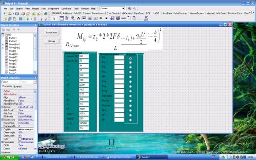
Picture 1 – Definition of twisting and bending moment
of main girder of bridge crane
For consideration of
stress-strain status in complex loading of span beams (tension – compression,
bending and torsion) except the usual geometric characteristic, its crossings and given powers it’s
necessary to determine some additional geometric characteristics of crossings
and the power factors were used Solid Work.
Having the conditions of
fastening an loading of span beams of box section of given longitude and lateral powers, that applied to the current case 1, warping
section will be different, that will give the appearance of additional, normal
and concerned stress of crossings, that could be achieved the volumes
comparable with the main bending stress. By load factor changing and trolley moving
we receive the loading of span beam, when the trolley is in the medium part, in
the picture 2 shows the stress-strain status of span construction (box section)
of bridge crane with 16T loading and span
length 16,5m, uplifting speed 0,14 m/c, trolley moving speed 0.71 m/c.
type of crane rail RP-50. From the
pictures we see that the medium part of the bridge under the trolley is the
more loaded. The constructed model of bridge crane is loaded with the different
capacity from 3.2t to 16t. After, the
model is created and it is entered all necessary corrections, it was done the
following actions: the first – fastening of the model, model dividing in the
final elements, the step of dividing is 200mm and after going to APM structure
3D, where with it calculates; the second – gives the appropriate loading: the
weight of trolley with uplifting mechanism, moving, (in the scheme shows the
trolley without mechanisms, but the weight of these mechanisms is taken into
consideration); estimates its stress-strain status. Loading map allows to
analyze the distribution of different internal reacted power factors (forces
and moments) during model construction elements using by the dialogue settings,
can be checking the results of components and normal stressing in the plane of
axes X and Y of local system of construction coordinates. From the picture 2
it’s seen, that the medium part of bridge under the trolley is more loaded.
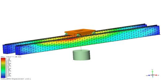
Picture 2 – Map of
equivalent stress model of the transit beam bridge crane when the truck in the
middle of the bridge
The conclusions:
· The right choice of constructive schemes and sections of steel
structures elements, calculation by using of modern programmes during hosting
machines exploitations provides them with the stability, rigidity and
durability.
· The strain stress status in the complex loading of span beam of hoisting
machines (tension-compression, bending and torsion) can be determined by the
method of final elements with the using of modern programmes.
· The map of equivalent stressing of model construction allows determining
the more loaded parts of constructions.
REFERENCES:
1. Vershinsky A.V. «Manufacturability and bearing capacity crane metallic»
- M.: Mawinostroenie, 1984.167 paper.
2. Alexandrov M.P., Gohberg M.M. « Reference cranes, Volume 1, 2» - L: Mawinostroenie,
1988.