Post-graduate student N.V.
Pronin
South Ural State University, Russia
The
basic principles simulation of WPU-3 (Wind Power Unit)
In
the present time, one of the most pressing problems of modernity is the problem
of energy saving. The level of economic development is the main indicator of need
for its speedy resolution.
The
use of renewable energy with energy efficiency equipment can provide
significant economic and ecological effects. Typically, in such systems a
source of energy (heat or electricity) is a kind of device that converts wind,
solar, water energy etc., necessary for us kind of energy.
Wind
Power Unit -3 produced by "SRC-Vertical" (Miass, Russia) as a transmitter
"the wind - electricity," uses the rotor WPU with blades and
synchronous generation on a permanent magnet with axial gap (Fig. 1) [1].
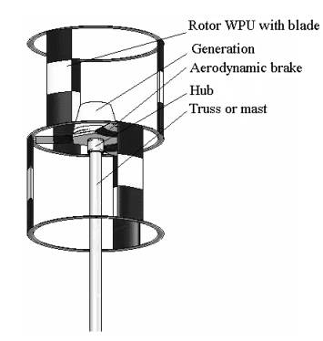
Figure 1 –The basic elements of WPU
General
characteristics of WPU are presented in Table 1. Considered source of
electrical energy can be paired with a variety of potentially low-power and energy
efficient consumers,
such as infrared heating
systems, pumps, and any appliances. No less interesting is the opportunity to
work with both the overall network, as well as with other energy sources. In all these systems as a source of electrical
energy can be used WPU-3. Therefore, a comprehensive study of this source, common
to different systems,
will enable its wide
application in many fields.
Table
1 – General characteristics of WPU
|
Rated power of generator, kW |
3 |
|
Rated wind speed, m/s |
10,4 |
|
Starting wind speed, m/s |
1 |
|
Range of wind speeds, m/s |
4–45 |
|
The maximum wind speed, m/s |
60 |
|
The range of speed, rev/min |
60–200 |
|
Rated
speed, rev/min |
180 |
|
Number
of blades, p |
6 |
|
The diameter of the rotor (wheel), m |
3,4 |
|
The height of the rotor, m |
3,8 |
|
Swept
area, m2 |
12,92 |
|
The height of mast, m |
8–20 |
The mathematical
model of WPU-3, which is presented in Figure 2 was constructed by using the software
package MATLAB.
The
model consists of the following components [2]:
Ramp – generate constantly
increasing or decreasing signal. The desired growth rate of 0.1
m/s2 winds ranging from 1 m/s;
Saturation
– limit range of signal. The specified speed limits 0 and13 m/s;
Math Function – perform mathematical
function, provides a quadratic dependence of the output
parameter of the input;
Gain – multiply input by constant, takes a
value multiplier – 1.97676;
Permanent
Magnet Synchronous Machine – model the dynamics of three-phase permanent magnet synchronous machine
with sinusoidal or trapezoidal back electromotive force. The mode of operation
is dictated by the sign of the mechanical torque
(positive for motor mode, negative for generator mode).
Universal Bridge – three-phase rectifier diode;
Powergui – graphical user interface;
RLC Branch
– consistent RLC circuit simulates the work of the rectifier smoothing
filter;
Display – digital Display;
Voltage Measurement
– voltmeter.
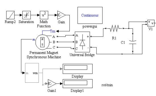
Figure 2 – Model wind turbine WPU-3
The
general principle of the mathematical model is:
To
block Permanent Magnet Synchronous Machine supplied a negative torque, which is determined by wind speed.
The
torque applied to the generator turbines, depending on the wind
velocity is equal to [3]:
![]() (1)
(1)
where
![]() - coefficient
of torque,
- coefficient
of torque, ![]() ;
;
![]() - density of air,
- density of air, ![]() ;
;
![]() - wind speed,
- wind speed, ![]() ;
;
![]() - swept area,
- swept area, ![]() ;
;
![]() - radius of rotor WPU,
- radius of rotor WPU, ![]() .
.
The
coefficient of torque ![]() is determined at
the maximum coefficient of using wind energy and rapidity(Fig.3), which is
defined as [3]:
is determined at
the maximum coefficient of using wind energy and rapidity(Fig.3), which is
defined as [3]:
![]() (2)
(2)
where,
![]() - linear
velocity of rotation, m/s;
- linear
velocity of rotation, m/s;
![]() - wind speed, m/s.
- wind speed, m/s.
Thus, the control system supports the rapidity ![]() , while providing maximum efficiency of use of wind
energy
, while providing maximum efficiency of use of wind
energy ![]() , with coefficient of torque
, with coefficient of torque ![]() .
.
Determine
the torque applied to the rotor generator:
![]() .
.
Therefore,
the torque applied to the rotor of the generator, is directly proportional to the
square of wind speed.
With
the help of blocks Ramp, Math Function, Gain describes the impact torque ![]() on the
generator.
on the
generator.
Operation
generator Permanent Magnet Synchronous Machine is described along the following
lines of equations associated with the rotor [2]:
 (3)
(3)
where
![]() - q and d axis
inductances;
- q and d axis
inductances;
![]() - resistance of the stator windings;
- resistance of the stator windings;
![]() - q and d axis currents;
- q and d axis currents;
![]() - q and d axis voltages;
- q and d axis voltages;
![]() - angular velocity of the rotor;
- angular velocity of the rotor;
![]() - amplitude of the flux induced by the permanent magnets of the rotor
in the stator phases;
- amplitude of the flux induced by the permanent magnets of the rotor
in the stator phases;
![]() - number of pole pairs;
- number of pole pairs;
![]() - electromagnetic torque;
- electromagnetic torque;
![]() - combined inertia of rotor and load;
- combined inertia of rotor and load;
![]() - combined viscous friction of rotor and load;
- combined viscous friction of rotor and load;
![]() - rotor angular position;
- rotor angular position;
![]() - shaft mechanical torque.
- shaft mechanical torque.
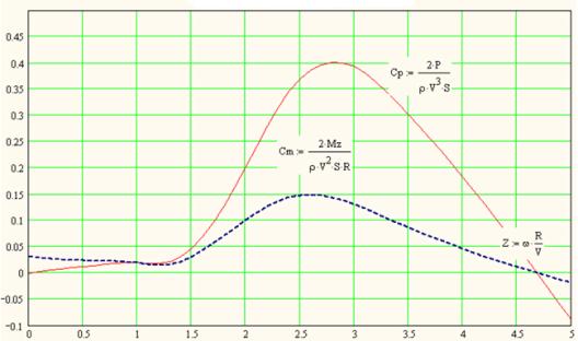
Figure 3 – The coefficient of wind energy ![]() and coefficient of
torque
and coefficient of
torque ![]() from the rapidity
from the rapidity
![]()
Block
parameters are presented in Table 2.
The
generator is a current source, alternating in phase, frequency and amplitude, which is difficult to use for the needs of the consumer. Therefore, the
voltage applied to the three-phase uncontrolled rectifier
bridge Universal Bridge. To smooth the ripple is the RC-filter with a time
constant much larger than the oscillation period of the current in the coil.
Table
2- Parameters of the block Permanent Magnet Synchronous Machine
|
The
form of the current |
sinusoidal |
|
Stator
phase resistance Rs, Оhm |
2,7 |
|
Stator
inductances [ Ld Lq ], H |
0,009 |
|
Flux
linkage established by magnets, Wb |
0,5 |
|
Inertia
J,
kg |
1118,43 |
|
Friction factor F, Nms |
0,85 |
|
Pole pairs |
25 |
The measuring the
output voltage with a voltmeter is V1, the frequency of the rotor with test
port m block of Permanent Magnet Synchronous Machine.
Figure 4 shows
the dependence of the rectified voltage from the rotor speed at idle mode ![]() , obtained by the simulation WPU-3 at package MATLAB.
, obtained by the simulation WPU-3 at package MATLAB.
Figure 4 – Characteristics of the idle mode WPU-3, resulting at MATLAB
Figure
5 shows the characteristics of idling mode,
measured during testing of the prototype generator.
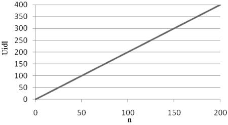
Figure 5 -Characteristics of the idle mode WPU-3, taken experimentally
Considered
the generator produces a nominal power of 3 kW at nominal 180 rev/min. These
values must be achieved at a wind speed 10.4 m/s. As a result of calculations
performed by the mathematical model presented in Figure 6 shows that when the
wind velocity 10.43 m/s was recorded speed of 180 rev/min, load current 9.8 A, the rectified voltage at the load of 309.8 V,
power 3036 watts, which confirms the close correspondence to the real parameters
of the model calculation model.
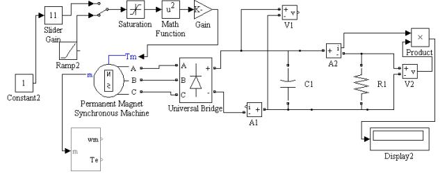
Figure 6 –Model of WPU-3 at work on the load
Conclusion:
1)
We
can talk about the behavior of the mathematical model under the real WPU-3;
2)
This model
can be used in the simulation of wind turbine control systems, modeling of energy systems based on wind
turbines.
3)
This
material shows the operation of WPU-3 and is applicable in
the study of this installation as visual aids.
References
1.
Solomin, E.V. Production / E.V. Solomin // Web-site «SRC-Vertical». –htttp://www.src-vertical.com – Chelyabinsk: 2007. – 1 p.
2.
Chernykh I.V. Simulation
of electrical devices in MATLAB, SimPowerSystems and Simulink / I.V. Chernykh, 2008. – 288 p.
3.
Kirpichnikova, I.M. The
transformation of energy in the wind power plants / I.M. Kirpichnikova, A.C. Martyanov, E.V. Solomin // Alternative Energy and Ecology, 2010. – №1. – p. 93–97.