Ensuring electrical safety in the power industry
Seitkassym A., Dildabek D., Akilova K.
M. Kh. Dulaty Taraz State University
Electrical safety in industrial conditions is ensured by the appropriate
design of electrical installations: technical methods and means of protection; organizational
and technical measures.
Provision of electrical safety in Hydroelectric
power station, where high-capacity electric power is generated from
accidental contact with live parts is achieved by the following technical
methods and means used alone or in combination with each other: protective
shells, protective barriers (temporary or stationary); safe location of
current-carrying parts; isolation of the workplace; protective shutdown; warning
alarm; blocking; safety signs.
Locks are used in electrical installations that require frequent work on
the fenced live parts of the electric power industry. Locks on the principle of
action are mechanical and electrical. Mechanical have latches of different
designs, which lock the turning part of the mechanisms in the disconnected
state. They are used in electric starters, circuit breakers, circuit breakers.
Electrical interlocks break the circuit with the help of special contacts
installed in the fence doors, covers and casing doors. These interlocks are
most advisable to use together with remote control of electrical installation
(Figure 1). In this case, the interlocking contacts (BC) are interlocked with
the door or lid, open or remove the supply circuit of the coil of the magnetic
beetle (MP). With such a circuit breakage of the control circuit and accidental
opening of the door is not dangerous, since the electrical installation will be
de-energized [1].
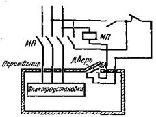
Figure 1. Diagram of an electrical interlock
In power plants, protective grounding, zeroing, shutdown, low voltage,
electrical separation of networks, isolation of live parts (working,
additional, reinforced, double), insulation monitoring, protective equipment
and safety devices are used to protect against touching metal non-conductive
structural parts of electrical installations.
Protective earthing is a deliberate electrical connection to the ground
or its equivalent of metal non-live parts that can be energized. It is an
effective protection measure for electrical equipment powered by voltage up to
1000 V from networks with isolated neutral. When the current-carrying parts are
closed on the equipment enclosure isolated from the ground, the latter will be
energized and touching it will be just as dangerous as the vase. Protective
earthing reduces the contact voltage to the housing to a safe level by reducing
the ground potential due to low ground resistance. The combination of metallic
conductors (grounding conductors) in direct contact with the ground and
conductors connecting electrical installations with earthing switches is called
a grounding device.
Depending on the location of the earthing switches, in relation to the
grounded earthing equipment, there are remote or concentrated, outline or
distributed. Earthing devices are natural and artificial. The natural include
various technological metal structures that have good contact with the ground,
reinforced concrete foundations, reinforcement of reinforced concrete
structures, metal cable sheaths (except aluminum), casing pipes, etc. For
grounding in the electric power industry, the available natural earthing
switches should be used first. Artificial earthing switches are specially
designed for earthing metal structures.
Grounding of electrical installations should be used in all cases at
voltage 380 V and above AC and 440 V and above DC, and also at voltages above
42 V, but below 380 V AC and 110 V DC in rooms with increased danger,
especially dangerous and in external electrical installations [1].
The objects to be grounded are connected to the grounding line with a
separate grounding conductor. Do not connect the earthing conductors from
several pieces of equipment consecutively, because in the event of a disruption
in the integrity of the connection, several electrical installations may be
ungrounded at once. The total resistance of the grounding device is equal to
the sum of the resistance to current flow from the earthing switches to ground
and the resistance of the grounding conductors.
To ensure safety, the resistance value of the grounding devices
according to the PUE should not exceed 4 ohms, and at a power of generators and
transformers of 100 kVA and less, the resistance of grounding devices is 10
Ohm. In electrical installations up to 1 kV with a dull-grounded neutral,
zeroing must be performed. This method of protecting a person from electric shock
in the event of a phase closure on the non-conductive parts of the electrical
installation is a deliberate electrical connection with a zero protective
conductor (Fig. 2).
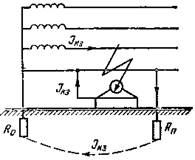
Figure 2. Zeroing
of equipment
The protective effect of zeroing is to reduce the duration of the short
to the housing and, consequently, to reduce the time of exposure of the
electric current to the person. When connecting the electrical enclosures to
the neutral wire, any short to the enclosure becomes a single-phase short.This
amount of current may not be enough to burn the fuse-link. In this case, the
body of the electrical installation will be under voltage, the value of which
may exceed the maximum permissible values for a person's touch
It is also unacceptable to use in a network with a deafly earthed
neutral the connection of a part of the electrical installations with zero wire
to parts earthed to separate earthing switches, since when the electrical
installations connected to a separate earthing switch are closed, the voltage
on it reaches a dangerous value. In this case, the enclosures of the electrical
installations correctly connected to the neutral wire will be under dangerous
voltage with respect to the ground.
Zeroing should quickly disconnect the damaged electrical installation
from the network and ensure the safety of the person's touch to the corps in an
emergency period. In accordance with this, the zeroing must be calculated for
the breaking capacity, as well as for the safety of contact with the housing
when the phase is closed to ground (neutral grounding calculation) and to the
housing (calculation of re-grounding).
Low voltage is the nominal voltage not exceeding 42 V, which is used to
reduce the risk of electric shock. In industrial conditions, the PUE provides
for the use of two small voltages - 12 and 36 V. Voltage up to 36 V is used in
rooms with increased danger, especially dangerous and outdoors for power of a
hand-operated electrified instrument, portable lamps. The voltage of not more
than 12 V inclusive must be used to power portable lamps in particularly
hazardous locations under particularly unfavorable working conditions: in
cramped conditions, when working with large metal grounded surfaces (working in
a metal container sitting or lying on a conductive floor, in a pit and other)
[1] [2].
Insulating coating of current-carrying parts or separating them from
other parts by a layer of dielectric in power plants ensures current flow along
the required path and safe operation of electrical installations. In electrical
installations, the following types of insulation are used: working, additional,
double and reinforced. Working is the isolation of current-carrying parts,
which ensures the normal operation of the electrical installation and
protection from electric shock. An additional is called insulation, which is
provided in addition to the working one to protect against electric shock in
the event of damage to it. Double insulation consists of working and additional
insulation. Reinforced - this is improved working insulation, providing the
same degree of protection as the double. In case of double insulation, in
addition to the main working part, an insulation layer is used on
current-carrying parts, protecting the person when touching metal parts that
are not live, which can be energized if the working insulation is damaged.
To ensure electrical safety in HPP as grounding device recommends first
of all using reinforced concrete foundations of industrial buildings. The
correspondence of their resistance to the permissible is determined by a
special calculation. The process of identifying this correspondence involves
the definition of the source data; calculation of the resistance of the
foundation; comparison of calculation results with acceptable resistance. In determining the initial data, the following
information is collected: the characteristics of the electrical installations
(type, types of main equipment, operating voltage, etc.); schemes and dimensions
of the reinforced concrete foundation of an industrial building along the outer
contour, limited by the basement parameter; specific electrical resistances of
the upper and lower layers of the soil [3].
In the power industry, personnel (not younger than 18 years old) who
have undergone medical examination, instruction and training in safe working
methods and who have a certain electric safety qualification group are allowed
to work for electrical installations.
Organizational arrangements that ensure safety when performing work in
existing electrical installations are the design of work by a dress or order,
admission to work, supervision during work, drawing up a break in work,
transferring to other jobs and finishing work [2] [3].
To ensure the safety of work in existing electrical installations with
partial or complete removal of voltage at workplaces the following technical
measures are performed:
• The necessary electrical installations or
parts thereof are switched off and measures are taken to prevent the supply of
voltage to the workplace due to errors or spontaneous switching on of
communication equipment;
• Prohibiting posters are posted and
temporary barriers are installed, if necessary;
• Portable grounding is connected to the
grounding bus and it is checked that there is no voltage on the live parts to
which the portable ground must be applied;
• Immediately after checking the absence of
voltage, grounding is applied to disconnect the live parts of the electrical
installation;
• The workplace is shielded and warning and
authorizing posters are posted [3].
Electric safety has always been and remains one of the
most important problems in the electric power industry. The alarming tendency
of the growth in the number of electro-injuries compared to the last decade is
due not only to problems in the electric economy of enterprises and
organizations (insufficiently high professionalism of electrical personnel,
non-compliance with norms and rules for work in electrical installations, poor
technical condition of electrical installations, etc.), but also a number of
objective reasons. One such reason is the fragmentation of large and
medium-sized enterprises with a well-established energy service and
well-functioning electric power in many small commercial organizations in which
the staff of electrical personnel is under-equipped and sometimes absent or
operates as part-time employees.
Bibliography:
1. GOST 12.1.019-2009. Occupational safety
standards system. Electrical safety. General requirements and nomenclature of
types of protection.
2. Fire safety rules for energy companies
(RD-153-34.0-03.301-00), M., "Energy Technologies", 2000.
3. Borisov L.G., Knyazevsky B.A., Kucheruk
S.M. Labor protection in power engineering. M., Energy Publishing House, 1985.