A method for constructing a finite element model for
the calculation of reinforced concrete bending beam in the theory of deformation
model.
A.A. Suvorov, Scientific Consultant Ph.D. V.G. Murashkin.
FGFEI «Samara State University
of Architecture and Civil Engineering»
Abstract. The technique of creating a
plane finite element model for the calculation of reinforced concrete beam
bending it in the theory of deformation model. The calculation is in the
nonlinear formulation is taken into account creep of concrete and building load
in walking-iterative design process calculations. Performed simulations of
crack and the final state of the beam in a deformed state within is based on a
flat bend.
Key words: deformation model, flat
bend, nonlinear analysis, creep of concrete stress-strain diagram, function
curvature.
Simulation of beam
produced in the PC "Lira" version 9.6, which realized the possibility
of a nonlinear calculation taking into account the creep of concrete according
to the method of Eurocode 2 [1]. The problem of modeling has solved in flat
system «XOZ» elements such as beam-wall.
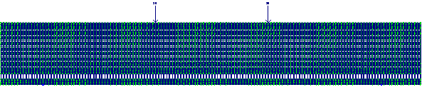
Fig. 1.0. Finite element model of reinforced concrete beam in the plane
problem PC "Lira".
As seen in Figure 1.0, the
beam was modeled in a longitudinal section with dimensions corresponding to the
actual dimensions of the structure, namely the section height - 220 mm; section
width - 120 mm; beam length - 1500 mm. Model
beam consists of four blocks: concrete beam body disposed above the reinforcing
bar, the contact area around the reinforcing rod, the rod itself valves Æ20The protective layer of the
concrete bottom. Load and communication have attached according to the design
scheme design.
The finite element mesh has
created from flat finite element (FE) beam-type wall to simulate plane stress. Geometric
dimensions TBE selected so that, firstly, the cross section corresponds to a
cross section model of the actual sample, secondly, has provided acceptable
precise position (height) of the crack tip, as well as the ability to analyze
the stress-strain state of the concrete in the zone his contact with the valve.
Concrete is modeled from
physically nonlinear finite element rectangular plane problem number 221 5 mm
along the axis «Z», and 10 mm along the axis "X" with the task of
stiffness characteristics for concrete class B30 (type "TA" - natural
hardening). The width of the data elements in the space for concrete, located
above and below the rebar is the real width of the beam section.
Contact zone reinforced
concrete is modeled by three thin layers of a thickness of 1 mm and a width of
10 mm TBE. The first (internal to the rebar) layer is modeled physically
nonlinear finite element rectangular plane problem number 281 (ground) with the
task of further traction, angle of internal friction, limiting tensile strength
for concrete contact zone. The second and third (external to the rebar) layers
are physically non-linear finite element rectangular plane problem number 221
with the characteristics of the material according to CE concrete. The width of
the contact zone is modeled equal![]() - semi perimeter corresponding reinforcing bar in order to get the
shear stresses corresponding to the actual contact surface. The presence or
absence of coupling is modeled respectively the presence or absence of elements
adjacent directly, facility to the reinforcing rod. When you reach the contact
tangential stresses the limits that have been taken to be 2Rbt,
interaction with concrete reinforcement is modeled as follows. Adjacent to the
reinforcing bar element in which the shear stresses have reached the limit
values destroyed, and to the reinforcement and concrete are
applied opposing force
- semi perimeter corresponding reinforcing bar in order to get the
shear stresses corresponding to the actual contact surface. The presence or
absence of coupling is modeled respectively the presence or absence of elements
adjacent directly, facility to the reinforcing rod. When you reach the contact
tangential stresses the limits that have been taken to be 2Rbt,
interaction with concrete reinforcement is modeled as follows. Adjacent to the
reinforcing bar element in which the shear stresses have reached the limit
values destroyed, and to the reinforcement and concrete are
applied opposing force![]() equal:
equal:
![]() (1.0)
(1.0)
where lk- length of the finite element.
 The body of the
valve has created by physically nonlinear finite element rectangular plane problem
number 221 with the dimensions of 20 mm along the axis «Z», and 10 mm along the
axis "X" with the task of reinforcement stiffness characteristics for
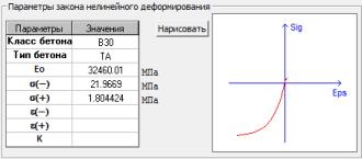
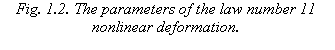
class A400. Deformation law has adopted for the main concrete and concrete
contact zone under number 21 - Exponential (standard strength) (Fig. 1.1.). For
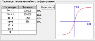
valves - 11th exponential law of deformation with the task to design resistance
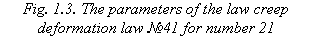
strength of the steel [2] (Fig. 1.2.). In a further menu (Figure 1.3) for the
stiffening of concrete parameters are set taking into account creep, calculated
by the algorithm in the environment «Mathcad» according to block coefficient
calculation creep in the Annex to Eurocode 2 [1].
The body of the
valve has created by physically nonlinear finite element rectangular plane problem
number 221 with the dimensions of 20 mm along the axis «Z», and 10 mm along the
axis "X" with the task of reinforcement stiffness characteristics for
class A400. Deformation law has adopted for the main concrete and concrete
contact zone under number 21 - Exponential (standard strength) (Fig. 1.1.). For
valves - 11th exponential law of deformation with the task to design resistance
strength of the steel [2] (Fig. 1.2.). In a further menu (Figure 1.3) for the
stiffening of concrete parameters are set taking into account creep, calculated
by the algorithm in the environment «Mathcad» according to block coefficient
calculation creep in the Annex to Eurocode 2 [1].
 Cracks are modeled jointing nodes in the development
of normal cracks. A method of modeling crack conducted according to the calculation
of crack opening width [1] and their development is in accordance with the
position of the main areas of tensile stresses that can more accurately
simulate the stress state of the concrete at the crack tip and to determine its
depth.
Cracks are modeled jointing nodes in the development
of normal cracks. A method of modeling crack conducted according to the calculation
of crack opening width [1] and their development is in accordance with the
position of the main areas of tensile stresses that can more accurately
simulate the stress state of the concrete at the crack tip and to determine its
depth.
For inclusion in the work of
these laws, nonlinear deformation produces a nonlinear load. In the nonlinear
static load, uploading has used in accordance with the design scheme design.
The number of steps of the load has selected independently. In the appropriate
boxes on settlement, periods creep of concrete specified n-th day since the
control of the load. The number of iterations - 300 [4].
When loading the beam is
considered appropriate n-th time period to attend the element creep of
concrete. In one of the sections where tensile stresses ultimate tensile
concrete in bending, reaching values of 1,75 Rbt, is
formed crack normal process of development which, in accordance with the
vertical trajectory of principal tensile stress is simulated serial jointing
nodes of the finite element from the lower edge of the side of the compressed
zone. Allowable precision overlay cracks according to calculations by Eurocode
2 was established and modeled on the sites of the principal stresses. The
position of the crack tip height section is set such that the principal tensile
stresses at the crack tip were equal or close to Rbt. After
determining the position of the crack tip is analyzed magnitude of tangential
stresses in the contact area and the elements (adjacent to the reinforcing
bar), in which the voltage reaches the limit (2Rbt), are eliminated,
and the interaction of reinforcement and concrete is simulated as mentioned
above, the application of oppositely directed efforts Nt. At the same time, as the destroyed adjacent to the
valve CE, controlled the main tensile stresses at the crack tip and, if
necessary, adjusted her position. Set out the process of development of the
crack, flowing at a constant load, corresponding to the moment of its
formation, continues as long as the shear stresses in the contact zone and the
normal stresses at the crack tip will no longer exceed 2Rbt and Rbt
respectively [3].
As determined by the point
of zero relative displacements reinforcement and concrete, and adjusted its
displacement. Moving the contact layer of concrete and reinforcement at zero
mutual displacement together, which allows its location to correct the error,
since it may be between the member nodes.
REFERENCES
1.
BRITISH STANDARDS INSTITUTION. BS
EN 1992-1-1, Eurocode 2: Design of concrete structures. General rules and rules
for building. BSI, 2004.
2. SP 63.13330.2012. Concrete and reinforced concrete
structures. The main provisions. The updated edition of SNIP 52-01-2003. Moscow, 2012.
3. A.A. Prokopovych
Bending resistance of reinforced concrete structures with different conditions
clutch armature with concrete. Samara, illegal armed groups "SMS",
2000.
4.
V.G. Murashkin, D.A. Panfilov, A.A. Suvorov.
Modelling of reinforced concrete beam finite element method taking into account
the creep of concrete / Tradition and Innovation in Building and Architecture:
Materials 70th Anniversary All-Russian Scientific and Technical Conference on
the results of R & D 2012 - Samara, 2013 - p. 307-308 - Part2