technical / mechanical
engineering
Nurmukhanova A.Z. Candidate of technical sciences, Mukhtarova M.N. Candidate of physical and mathematical sciences, Nurseytova A.K.,
Konakbaev B.O.,
Zulbukharova E.M., Ermaganbetova S. D.
Kazakh National University named after Al-Farabi, City
of Almaty
Republic of Kazakhstan
THE NEW CONSTRUCTION OF THE CENTRIFUGAL MIXER
The
main object of the invention is to improve the device performance by
accelerating the process of mixing the mixture of fractions and lowering energy
costs of the blending process.
The
technical result is achieved in that the centrifugal mixer cyclic operation,
consisting of a cylindrical mixing drum having a rotational axis extending from
the top to the bottom point of the bottoms of opposing intersecting the axis
through the center of gravity of the drum at an angle ![]() lying in the range 30-60°, the minimum value of which equal to or greater than
the angle of repose of the material loading of 30° and longitudinal projections
inside.
lying in the range 30-60°, the minimum value of which equal to or greater than
the angle of repose of the material loading of 30° and longitudinal projections
inside.
For
example, if the ratio is rational ratio of the length of the drum to its
diameter![]()
![]() is
equal to the angle
is
equal to the angle![]() of 39 °, which is greater than the angle of repose of the material for download
in motion.
of 39 °, which is greater than the angle of repose of the material for download
in motion.
When
p=1; 1.25; 1.5 respectively 45°, 39°, 30°, where the lower value of the angle ![]() =
30 ° is chosen equal to the angle of repose of the material in the loading
movement.
=
30 ° is chosen equal to the angle of repose of the material in the loading
movement.
The
invention relates to construction equipment and in particular to the structural
design of the mixer used to prepare mortars, for example of concrete.
The
proposed mixer will be used in construction, in the preparation of construction
mortars and concrete. Operation of the mixer will significantly increase the
productivity of the process while reducing energy consumption.
Set
of claims:
-
The centrifugal mixer consists of a
mixing drum, rotatable about an axis, wherein the axis of rotation of the mixer
is directed at an angle α, which lies in the range of 30-600 to the
geometrical axis and intersects it in the center of the drum and the axis of
rotation passes through the upper line lower point and the opposite end
surfaces of the cylindrical mixer.
-
A centrifugal mixer according to
claim 1, characterized in that the inner surface of the cylindrical mixer
provided with protrusions extending along the drum.
Known mixer centrifugal gravity (А.с. 245607 USSR , МКИ В28С, pub.
04.06,1969, bul. 19) having a part of the feed screw rotating mixing drum with
down-dropped knives, water supply system. The disadvantage of this mixer is the
complexity of the design, the presence of a larger number of parts.
Known mixer of gravity type, taken as a prototype, (KOROLEV К.M. «Mobile
concrete mortar mixers and concrete solutions pumping stations ». Art. 2, - М,
High School, 1991 ,p.30) consisting of a mixing drum rotatable around its
geometric axis on the inner surface of the drum are blades. Disadvantage of
this design is the low productivity of the process mixture, high levels of
energy mixing process.
Figure 1 shows a centrifugal mixer. The centrifugal mixer consists of a
cylindrical drum 1 is fixedly mounted on the shaft 3, so that the drum rotation
axis intersect at an angle with the geometrical axis of rotation of the drum.
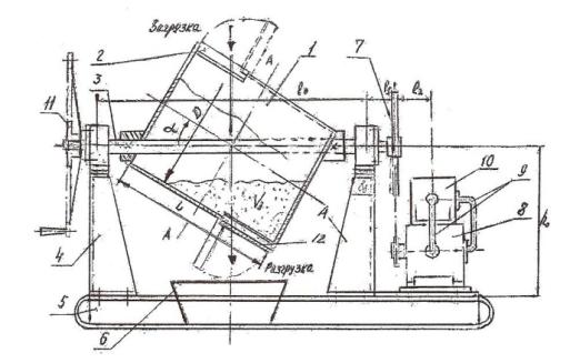
Figure 1 - Diagram of a centrifugal mixer
Drum 1 has two windows that are used to load and closing hinged lid 12.
The drum 2 and the shaft 1, 3 is mounted in bearing units struts 4 are mounted
on the frame of the mixer 5, in which there is a discharge chute 6. The shaft 3
of the drum, the transfer 7 is connected to the hydraulic motor 8, which
pressure and return line 9 is connected to a regulated hydrodrive
10 mounted on the frame of the mixer.
On the drum shaft 1 has a manual actuator 11 for rotating the drum and
unload the mixture during a power failure.
The mixer operates as follows. When you open the lid 2 of the upper
windows are downloading drum 1 components of the concrete or mortar mixture,
then top window is closed and the hydraulic motor 10 and 8, resulting in the
rotation of the drum 1 through 7 of the chain drive.
During the rotation of the drum is loaded into it the mass of material
mixture is poured simultaneously in two directions along the rotation of the
drum and along its axis, making complex spatial movement that promotes quality
(homogeneity) mixing and reduce the mixing time.
When the rotational speed of the drum 1 is controlled deceleration oil
from the hydraulic circuit 10 depending on the desired composition and quality
of mixing of the components in the incoming-prepare concrete or mortar.
After preparation of concrete or mortar mixer stops in the position
shown in (Figure 1). Windows are opened and the drum 1 is discharged into the
mixed product hopper 6. After discharge, if necessary, washed with water drum
1, the bottom of a hopper window 6 closed by a cover 12, and through the top
window is downloaded component mortar or concrete mix for the next batch. Then
the window is closed with an upper lid 2 and the hydraulic actuator 10 turns
the drum rotation cycle and repeated mixing.
Advantages of the above described construction of the mixer according to
(Figure 1) compared to known types of mixers by cyclic open cavities, with and
without paddles inside them is that:
-
Faucet has a simple structure in
which there are longitudinal projections within the drum and no tilting
mechanism for discharging and its hydraulic adjustment allows different speed
and direction of rotation of the drum;
-
Due to the asymmetry relative to the
axis of rotation of the drum takes place process intensification mixing the
mixture components, by steric bulk material handling load inside the drum in
the circumferential and axial directions simultaneously, which leads to a
reduction of the mixing time and, consequently, better performance mixer
-
The proposed mixer during operation
is closed, the inner cylindrical cavity, which eliminates the release of the
mixture out at high speeds of rotation of the drum.
In addition, for mobile mixers, low-capacity, a manual drive from the
handle 11 is mounted on the end of the shaft 3. In this case, the drive chain
gear 7 is released.
Literature:
1.
Nurmukhanova A.Z., Povetkin V.V., Sosnin V.А. Certificate of authorship № 66405 Centrifugal mixerfrom 15.12.2010,
bul. № 12 s. Astana.
2.
Nurmukhanova A.Z. Evaluation of the
technical condition of the equipment stationary concrete preparatory works.
//Proceedings of the X Anniversary International Scientific Conference
"Science and Education - a leading factor in the strategy" Kazakhstan
- 2030 ". Issue 2 -Karagandy, 2007. - P.454 – 456.
3.
Nurmukhanova A.Z. Analysis of the
causes of failures betonoprigotovitelnyh installations. //Proceedings of the X
Anniversary International Scientific Conference "Science and Education - a
leading factor in the strategy" Kazakhstan - 2030 ". Issue 2 -
Karagandy, 2007. - P.457 – 459.
4.
Erehinsky V.V. Efficiency and
quality of construction. Gorkiy: Volga - Vyatka book. publishing house, 1981.
-223 p.
5.
Kessel L.A. Cost-effectiveness of
new technologies and methods for its determination. – М.: GosINTI, 1976 y.