Технические науки / 4.
Транспорт
Alexey
Shabelnikov
The author of the SECU-3.ORG
project, Ukraine
MICROPROCESSOR
CONTROLLED IGNITION SYSTEM
SECU-3 MICRO
Nowadays,
a lot of old vehicles with contact/distributor based or legacy and/or out of
production distributorless electronic systems are still in use. Spark-ignition
(SI) engines with distributors and especially with contact distributors can't
meet modern economy, power and ecological requirements [1]. Also, if legacy
electronic control unit go down, in majority of cases it can't be replaced,
because it is out of production. One of solutions is to develop ignition
control system using modern components, based on microprocessor. Such systems
are flexible, adaptive and therefore can be easily tuned.
The aim of this work is to
develop microprocessor ignition control system, which will be cheap and open
source − SECU-3 Micro (SECU-3M) [2]. The main input requirements of the
system are following:
▪
open source software [2; 3];
▪
cheap and widespread electronic components;
▪
double sided printed circuit board (PCB);
▪
USB interface;
▪
2 low power ignition outputs (so, wasted spark configuration can be used
on 2 and 4-cylinder engines);
▪
coolant temperature sensor (CLT) support;
▪
crankshaft position variable reluctance (VR) sensor or
Hall-effect/optical sensor support;
▪
wireless communication via Bluetooth;
▪
measuring board voltage;
▪
input for intake manifold pressure (MAP) sensor;
▪
input for throttle position sensor (TPS) or simple throttle limit
switch;
▪
input for switching between two sets of maps (e. g. for
gas/petrol).
Schematic diagram of the
SECU-3 Micro unit is shown on fig. 1. The core of the system is microcontroller
U3 (ATmega644), which is run on 20 MHz and uses external crystal oscillator.
Connector J2 is for in-system programming (actually it is needed only one time −
for writing out boot loader). There are two jumpers near to microcontroller: J5
and J6. First one is for starting boot loader (intended for use in emergency
cases, e. g. when firmware is broken and boot loader doesn't start
automatically). Second one is for loading backup or factory settings in to electrically
erasable programmable read-only memory (EEPROM).
Light emitting diode (LED) VD2
is for diagnostic purposes (like «Check Engine» lamp). Because system is
relatively simple (no big demand in diagnostics), it is left on PCB. USB
interface is built on integrated circuit (IC) U1. Bluetooth module is shown as
U6. It is separate PCB module, mounted on main PCB by means of 4 pins. We
will not see deep into Bluetooth module in this article.
All discrete and analog inputs
are protected by simple resistor-capacitor circuits (RC circuit). Mentioned
circuits on analog inputs (PA0, PA1, PA2, PA5 pins of U3) also act as simple
anti-aliasing filters [4] for analog-to-digital converter (ADC). ADC uses
reference voltage of 5V. CLT and TPS inputs have optional pull up resistors,
using of which can be configured on PCB. GAS_V input has pull-down resistor
(R12).
IC U5 (comparator) forms input
signal conditioner for crankshaft position (CKP) sensor. This input has optional
pull up resistor (R13), which is needed when sensor with open collector (drain)
output is connected (e. g. Hall-effect or optical sensor). Connecting of
R13 can also be configured on PCB.
Two ignition outputs are built
on transistors VT1 and VT2 with pull-up resistors at inputs and outputs. Diode
VD1 is optional and useful for inductive loads.
Supply for external sensors
(e. g. MAP, TPS or Hall-effect) is decoupled from internal 5V supply using
inductance L2 and capacitor C18.
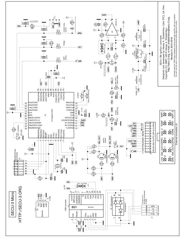
Fig. 1 − Schematic diagram of the SECU-3 Micro ignition control unit
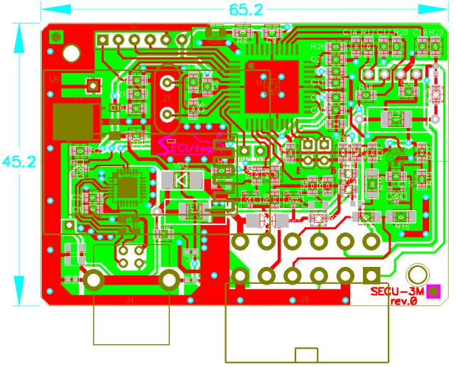 PCB design of the
SECU-3 Micro unit is shown on fig. 2. PCB is double sided and is designed for
mounting into a KM-86 enclosure. Bluetooth module is shown on fig. 3.
PCB design of the
SECU-3 Micro unit is shown on fig. 2. PCB is double sided and is designed for
mounting into a KM-86 enclosure. Bluetooth module is shown on fig. 3.
 Fig. 2 − PCB design of the SECU-3 Micro unit
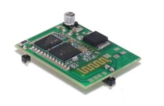
Fig. 3 − PCB
of the Bluetooth module
The most typical wiring
diagram of the SECU-3 Micro unit is shown on fig. 4. In this example only
one ignition output is utilized, used single coil with mechanical distributor.
This configuration is very simple and cheap and can be used for
2, 3, 4, 5, 6, 8-cylinder engines. For 1-cylinder
engines distributor is not necessary. On 2- and 4-cylinder engines wasted spark
(distributorless) [5] configuration can be used (in this case additional ignition
module should be connected to IGN_OUT2 output). If IGN_OUT2 output is
not used, then it can be remapped in software for other functions (for
instance: fuel pump control, tachometer output,
shift light etc.).
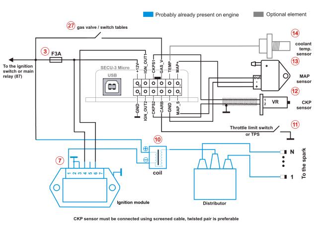 Fig. 4 − Example of SECU-3 Micro wiring diagram
So, in the article the main ideas and development of the
«SECU-3 Micro» ignition control system are briefly
described. One can see that this system doesn't contain knock sensor
support, integrated ignition coil drivers, plenty of outputs etc, but presence
of mentioned features would lead to a substantial rise in the cost and
complexity of the system. There will be
development of firmware for this unit soon and upcoming testing in laboratory
and on real engines. Author plans to extend
firmware capabilities related to synchronization options and some engine types
(e. g. V-twin) in the future.
References
1.
Транспортная
экология: учеб.-метод. пособ. [для студ. всех
форм обуч. бакалавриата по напр. 280700 «Техносферная
безопасность» (профиль «Безопасность жизнедеятельности в техносфере»)] / сост.
А. Г. Илиев, И. А. Занина. – Шахты: ИСОиП (филиал) ДГТУ, 2014. – 74
с.
2.
МПСЗ
SECU-3 / Ignition and fuel injection ECU [Electronic
resource]:[Site]. − Access mode: http://secu-3.org/.
3.
FreeEMS [Electronic
resource] : [Site]. − Access mode: http://freeems.org/.
1.
Smith, S. W. The Scientist and
Engineer's Guide to Digital Signal Processing /
S. W. Smith; 2-nd Ed. −
San-Diego: California Technical Publishing, 1999.
− 650 р.
2.
Reif, K. Gasoline Engine
Management: Systems and Components (Bosch
Professional Automotive Information) / Konrad Reif. − Wiesbaden: Springer
Vieweg, 2015. − 354 р.