Dmitriy A. Plugin, PhD, Docent, Arkadiy N. Plugin, DSc, Professor,
Aleksei A. Plugin, PhD, Olga S. Borzyak, PhD
Ukrainian State
Academy of Railway Transport, Kharkov, Ukraine
ELECTRO-CORROSION OF
CONSTRUCTIONS OF RAILWAY
TUNNELS
The operational reliability of concrete, reinforced
concrete and stone structures and rail supports depends on ability of their
constructions to resist the destruction of leakage current and stray current. The
existent notions and current standards take into account that destroying influence
renders only a direct current and only in the anodal zones of metallic
constructions and armature of reinforced concrete constructions. However recently
the researchers of Ukrainian State
Academy of Railway Transport got a new information and developed the hypotheses
that a cement stone and concrete is also exposed to electro-corrosion from the
action of direct current. The fact that in some tunnels, which are built and exploited in accordance
to current standards, unforeseen considerable corrosive damages are marked.
Character of electric current flowing through concrete and cement
stone of constructions. A railway contact line energizes
from traction substation and divided on sections (fig. 1). Sections are
isolated one from other by sectional delimiters and insulating rail joints.
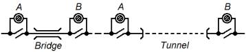
Fig. 1 – Scheme of the
longitudinal sectionalizing of contact line [1]: A, B are sectional delimiters
The rails are the return line of contact line of
every section. At a motion of train on a section there is an area with positive
potential on rails under an electric locomotive. Thgis area moves at a speed of
the train (fig. 2). When the train leaves a section the potential disappears,
so the a current and potential are not direct, but pulsating unidirectional.
Some part of pulsating unidirectional current flows down from rails through
rail-fastening clip, sleepers (including through the concrete of sleeper) and
ballast in ground (fig. 2).
Fig. 2 – The scheme of
traction current flowing down from a rail track and distributing of potentials
along rails at the one-sided power of section [2]:
TS – traction substation; EL –
electric locomotive; І – traction current; Іr – current in rails; Іg – current in ground; Ur-g – potential difference “rail – ground”; 1 – values at the complete isolation of rails from
ground; 2 – actual values
A current from rails flows also through constructions of tunnels in a ground.
Measured potential difference between a rail and a
distant point of earth, between the tunnels constructions and distant point of
earth (fig. 3 – 5) testify to the presence of such currents [3 – 7].
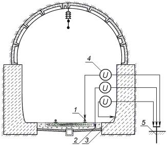
Fig. 3 – The scheme of potential measurement on the rail of the electrified track, ballast
and surface of facing the tunnel: 1 – rail, 2 - ballast, 3 -
facing the tunnel, 4 - measuring
equipment, 5 - grounding electrode
a) |
|
|
b) |
|
Fig. 4 – Dependence of potential in relation to the distant
point of earth U, V, from
time Hour:Min:Sec: a – on the rail, Umax = 115,6 В (12:06:05); b – on the
concrete surface of facing the tunnel, Umax = 2,99 В (12:06:36) [3]
a) |
|
|
b) |
|
Fig.
5 – Dependence
of potential in relation to the distant point of earth U, V, from time Hour:Min:Sec: a – on the rail, Umax = 49,95 В (12:52:25); b – in a ballast under the
railway sleeper, Umax
= 3,657 В
(12:53:51) [3]
Basic
hypothesis of researches. Pulsating unidirectional electric potential and current stipulates the
electro-corrosion of concrete. This electro-corrosion consists in
intensification of leaching of cement stone and formation of cracks in a
concrete due to the dissolution and electro-migration carry-out of calcium
hydroxide in a water or water-saturated ground [6 – 10]. The amount of the
calcium hydroxide carried out from the concrete depends on the amount of the
transferred electric charge [8, 9].
Method
of experimental researches of the pulsating unidirectional
electric potential and current influence
on a concrete. Experimental researches were done to prove the hypothesis of the
destroying action of pulsating unidirectional potential and current on a
concrete. The special laboratory installation for such action concrete was
developed and made [6 – 9]. Samples-cubes of sizes 100×100×100 mm made from a
concrete by strength about 10 MPa were made for researches. Composition of concrete
on 1 m3: cement – 167 kg, broken stone – 1310 kg, sand – 667 kg,
water – 200 liters, W/C = 1,2. Steel perforated plates - electrodes were set on
the top and bottom face of samples.
Samples-cubes were placed in the capacity of the
laboratory installation in a water on ¾ of their height. On the top and
bottom plates - electrodes with help of the programmable power source the feed
of potential difference was realized by the regime 7 minutes – turned on, 10
minutes – turned off. Such regime approximately corresponds to the intervals of
trains passing. The influence of voltage of 40, 15 and 5 V at a stream of water
through the capacity was researched. Such voltages correspond to the potential
sizes on rails. Control samples were in a running and stagnant
water without influence of current.
The readings of voltage, strengths of current,
electric resistance of sample registered by the measuring devices and
automatically recorded on a personal computer. After the protracted influence
of pulsating unidirectional potential and current and running water, and also
exposure of running and stagnant water on the control samples the compression
strength, loss of strength, non-pressure
water-permeability were determined.
Physical-chemical researches – X-ray phase analysis, infrared spectroscopy,
light and scanning electronic microscopy also were done.
The results of research of
influence of pulsating unidirectional electric potential and current on a
concrete. Graphs of dependence of strength of current I in samples from time at the protracted influence of
pulsating unidirectional electric field at 40, 15 and 5 V are presented on a fig.
7–a. The current at the end of every impulse is less, than at the
beginning of impulse. Dependence of this difference of current at the beginning
and at the end of every cycle DI presented on a fig. 7–b. The carry-out of cations of Ca2+ from the concrete sample
through its bottom face causes this difference of
current. Dissolution of Ca(OH)2,
electric potential and stream of water maintain this permanent carry-out.
a) b)
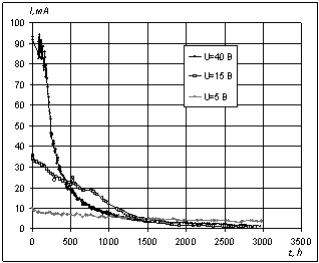
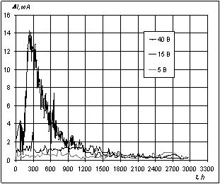
Fig. 7 – Dependence of strength of current I, flowing through the concrete
sample (a), and difference between
the strength of current in a sample at the beginning and at the end of a cycle DI (b) from time t at the continuous action
of pulsating unidirectional electric field at voltage of 40, 15, 5 V on
the samples
Quantity of charge Q, which is carried-out
from the investigated sample:
 , (1)
, (1)
where: ΔIi is a difference between strength of
current in a sample at the beginning and at the end of a cycle, A; ti - duration of cycle, s; n - quantity of cycles.
Mass m Ca(OH)2, which is
carried-out together with cations of
Сa2+ from the investigated sample, determined by
the size of Q:
![]() , (2)
, (2)
where: M – molecular mass of Сa(OH)2, 74 g/mole; F – a
number of Faraday, 9,65´104
C/mole.
The sizes of DIi and ti for
every cycle were put in (1) and (2) and got the data for the graphs of
dependences of carried-out the quantity of charge Q, С and Сa(OH)2
m (% from its initial quantity) from time of electric field action at voltages 40, 15 and 5 V (fig.
8).
a) b)
Fig.
8 – Dependence of electric charge quantity taken away from the concrete sample Q
(a) and quantity of Ca(OH)2
(from initial) taken away from the sample, % (b), from time t at a voltage of 40 V (upper curves), 15
V (middle curves) and 5 V (lower curves)
On the graph (fig. 8) the size of taken away charge
after 90 days was Q = 8500 C. It corresponds to the mass of taken away Ca(OH)2 m = 6,5 g, or 52 % from its initial
quantity (fig. 5). As a result of calcium hydroxide carry-out the strength of
concrete decreases, and its permeability increases and also its protective
properties in relation to an armature are lost.
The speed of Ca(OH)2 carry-out
from the sample at the voltage of 15 V less approximately in 2,5 times, and at
5 V – in 7 times. However, such speed of carry-out considerably will reduce the
term of service of concrete constructions. By the graph on a fig. 8-b at the 5 V the Ca(OH)2
carry-out for 90 days made 6,4 % from an initial quantity. The complete Ca(OH)2
carry-out at the 5 V
will happen approximately after 1300 days, all of CaO of a cement –
after 2600 days, and all of crystalline hydrates – after 5200 days or 14 years.
The state of constructions at a similar conditions for the same time confirms the reality of such speed of
concrete electro-corrosion.
It is set that the
action of electric field at the 40 V stipulated the considerable increase of
porosity and non-pressure water-permeability, and also the loss of mass. The
loss of mass of samples practically coincided with calculation values. The
strength of concrete in the zone of water flowing after 104 days of electric
field action has decreased compared to a sample that was only in running water
by 16 %, in stagnant water by 18 %. The results of experiments convincingly
testify to considerable intensification of leaching under the action of
electric field even at the 5 V.
Literature
1. Котельников А.В. Блуждающие токи
электрифицированного транспорта / А.В. Котельников. – М.: Транспорт, 1986. –
279 с.
2. Справочник по электроснабжению железных дорог. – Т.2 / [Под
ред. К.Г. Марквардта]. – М.: Транспорт, 1981. – 392 с.
3. Плугін
А.А. Проведення досліджень корозії елементів верхньої будови колії в залізничних
тунелях, визначення їх термінів експлуатації та розробка заходів щодо їх
захисту від корозії / [А.А. Плугін, А.М. Плугін, С.В. Мірошніченко та ін.] // УкрДАЗТ. – Х.: 2010. – Звіт з НДР № 60/3 – 2010. – 413с.
4. Плугін Д.А. Оцінка можливого
впливу замкненого простору в тунелі на величину потенціалу на рейці [Текст] /
Д.А.Плугін, А.М.Плугін, А.А.Плугін, О.С.Тіряєв. – Харків: УкрДАЗТ, 2011, вип.
127, с. 175-183.
5. Плугін
А.А. Аналіз впливу агресивних дій на конструкції та споруди залізниць: Верхня
будова колії в залізничних тунелях [Текст] / А.А.Плугін, А.М.Плугін,
Д.А.Плугін, О.С.Борзяк, О.О.Скорик, О.А.Конєв. – Харків: УкрДАЗТ, 2011, вип.
122, с. 187-201.
6. Plugin A.N. Research of influence
of leakage currents and stray currents on railways on buildings and
constructions / [A.N.Plugin,
A.A.Plugin, Al.A.Plugin et al.] // 17 Internationale Baustofftagung, 23 – 26 September 2009,
Weimar, Bundesrepublik Deutscland: Tagungsbericht. – Weimar: Bauhaus – Universität
Weimar, 2009. – Band 2. – P.1151 – 1156.
7. Плугин А.Н. Исследование влияния токов утечки и
блуждающих токов на здания и сооружения, расположенные возле
электрифицированных железнодорожных путей / [А.Н. Плугин, Ал.А. Плугин, А.А.
Дудин и др.] // Вісник НТУ «ХПІ». – 2009. – № 40. – (Серія: Хімія,
хімічна технологія та екологія). – С. 88 – 104
8. Плугин Ал.А. Исследование влияния величины напряжения
пульсирующего однонаправленного постоянного электрического поля на электрокоррозию
бетона /
Ал.А. Плугин // Збірник наукових праць УкрДАЗТ. – 2010. – Вип. 115. – С. 56 – 67.
9. Борзяк О.С. Исследование состава
водной среды, контактирующей с бетоном, подвергающимся электрокоррозии / О.С. Борзяк,
Ал.А. Плугин, Д.А. Плугин // Вісник НТУ «ХПІ». – 2011. – № 27. – (Серія: Хімія, хімічна технологія та екологія).
– С. 138 – 145.
10. Плугин А.Н. Основы теории твердения,
прочности, разрушения и долговечности портландцемента, бетона и конструкций из
них: монография в 3 т. / [А.Н. Плугин, А.А. Плугин, О.А. Калинин и др.]. – К.: Наукова думка, 2012. – Т. 3:
Теория прочности, разрушения и долговечности бетона, железобетона и конструкций
из них. – 2012. − 288 с.