O. Yaremchuk, Е. Gurinovich
Petro Mogyla Black Sea
national university, Ukraine
automated control system
of illumination
in the laboratory of
physics
Formulation of the problem and its connection with important scientific and practical tasks. As you know, high level of light in the room creates a feeling of
discomfort and rapid eye fatigue. It also can damage the light-sensitive plants
in the absence of the owner. Especially when the sunlight gets into the room.
Low illumination also can lead to negative results [1-3].
Previous studies of light level in the room (E(t))
show that lighting is much more than “comfortable level”, especially in the
period from 9 to 16 hours.
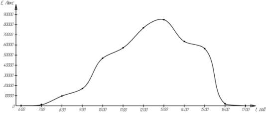 Pic.1.The illumination dependence on time
The purpose. Based on necessity of supporting the required level of light, it was
decided to create a device that would support the required level of light and
would be cheap enough for widespread implementation. The device consists of
three main functional units (excluding the power supply): unit conversion
parameter into electric light level setting (sensor); unit which processes the
receiving data of light level and controlsthe actuator and artificial lighting;
actuator and relay which turns on an artificial lighting, which functional
diagram is shown in the Pic.2.
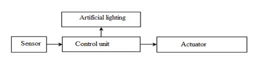
Pic. 2.
Functional scheme
Sensory(touch)
block consists of two photoresistors FR12/100К (for
averaging).Received data about illumination level and control processing block
is based on MC ATmega 8. To convert photoresistors values into digital values are used two ADC channels
built into the MC. This block also includes power transistors to transfer from
5 volt MC signals to 15volt (they need for work of the executing
mechanism(actuator)), relay for turning on artificial lighting and indicator,
which is used for visual control of illuminating
level.
Flowchart
algorithm of work of the MC is shown on the pic. 3. [4,5]
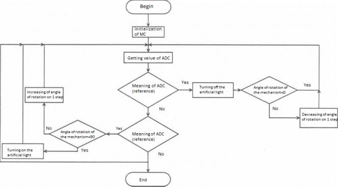
Pic. 3. Flowchart algorithm of work of the MC.
As you can see on the flowchart, MC has easy algorithm of work: using
the ADC value, MC compares actual level of illuminating intensity with
references (standard level) and decide the direction of engine rotation and, as
a result, opening or closing blinds. It also turns on artificial light, if
blinds are completely opened, but actual level of illuminating is lower than
reference, or turns off artificial light, if blinds are completely opened and
actual level of illuminating intensity is higher than reference. The reference
light level is non-volatile and could be changed by user in any time.
The executing mechanism (actuator) consists of stepper motor to rotate
the blind. Part of the program, which is responsible for control of executing
mechanism and relay of turning on artificial light is shown on the Pic. 4.
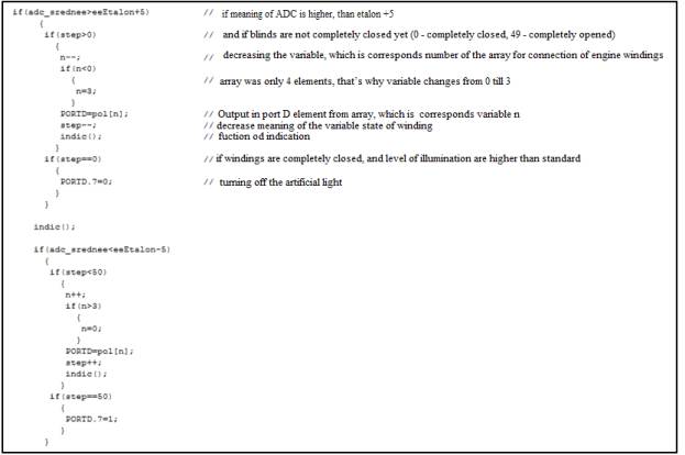
Pic. 4. Control of executing mechanism and
relay of turning on artificial light
Let’s consider an
electrical key diagram of the device, shown on the Pic. 5. Resistors R1-R4,
R14-R18 reduce current difference overcharge of transistor locks (gate) VТ1-VТ9
when they are switched into opened/closed status. Resistors R5-R11 limit the
current of indicator segments. Resistors R12, RІЗ, LDR1 and LDR2 form tension
divider, which middle point is connected to ADC MC. Resistor R-19 reduce
probability of accidental reset of MC, which can cause electromagnetic
disturbances. Transistors VT1-VT9 used for switching indicator category,
windings of stepper motor and relay of artificial light, as they use more
current than MC could give. Also for approval tension of signals of MC and
power supply of motor and relay. Diodes VD1-VD5 protect the scheme from tension
emissions when switching motor and relay.
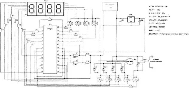
Pic. 5. An electrical key diagram of the
device
In the table number
1 are prices of components, which this device involve and its total value. [6-8].
Table 1
Prices of components and total value of the
device
|
Name |
Model/Characteristics |
Count |
Price for 1,hrn |
|
Indicator |
FYD-5622FS-11(general
anode) |
2 |
5,50 |
|
MC |
ATMEGA8A-PU |
1 |
22,00 |
|
Transistors: |
|
|
|
|
1) |
IRLML6402TR/20V;3,7A;SOT23 |
4 |
1.10 |
|
2) |
IRLML2803/30V;1,2A
SOT23 |
5 |
1,25 |
|
Stablilizer |
7805 CV/+5V,1.5A
TO220 |
1 |
1,55 |
|
Photoresistors |
FR
12/100k/6-18kOm 175 mW |
2 |
10,50 |
|
Resistors: |
|
|
|
|
1) |
100 Оm/SMD0805 |
9 |
0,08 |
|
2) |
360 Оm/SMD0805 |
7 |
0,08 |
|
3) |
10 kОm/SMD 0805 |
3 |
0.08 |
|
Capacitors |
1000 µF*25
V |
2 |
1,25 |
|
Protectiondiodes |
LL4007/1А 1000VDO 213АВ |
5 |
0,16 |
|
Powersupplyunit |
PW-12-2/12V 2А |
1 |
98,00 |
|
Stepper motor |
SY28STH51-0674A/Current of
winding-0.67 A. Retention time – 1200 g,cm |
1 |
250,00 |
|
Relay |
HLS-4078-DC12V-2C/HLS-4078-DC12V-2C |
1 |
8,50 |
|
Total |
|
|
427,52 |
Counclusions:
Economic profit. Using in rooms with two-three windows it is necessary only to increase
the number of engines and to add the unit with transistors, which are able to
let through more current. It allow store duce “specific” value of the device
for one window. But with the increasing of the number of windows, which blinds
are controlling from the one device, you need to consider hindrances, like
buildings, trees etc. more carefully.
Wideusingrange.This device can be used in
everyday life, offices, in high educational establishments, production rooms
etc. However it must be considered, that with increasing of linear dimensions
of the window, increases efforts, which is need for rotation of the slat of
blings.