Doctor of
Science Yu. V. Khrushchev, Candidate of Science N. L. Batseva , postgraduate
student L. V. Abramochkina
National
Research Tomsk Polytechnic University, Russia
The method of identifying
of overhead power line attenuation parameters in prefault conditions
Abstract
This report provides the idea of identifying of overhead
power line parameters on base of current and voltage instantaneous values
registered by Emergency Signal Recorders in prefault conditions.
Keywords: Overhead
power lines, power network, identification of fault location, line attenuation
parameters, Emergency Signal Recorders, current and voltage instantaneous
values.
I.
Introduction.
One of the reasons for
error appearance concludes using of line attenuation parameters specifically: r0,
x0 – active and reactive
resistances, [Ohm/km]; g0,
b0 – active and reactive
conductivities, [1/Ohm∙km]. In result of using attenuation parameters in
calculations consequences of lines operation are not taken into account for
example environment influence, thermal affects, ground conductivity. Hence
increasing of accuracy of fault location identification can be achieved by
means of real line parameters during determination of fault point on overhead
power lines.
II. Theoretical analysis.
For the moment the Emergency Signal Recorders
are widely used in power networks. These units allow to measure and record
current and voltage instantaneous values, which include adequate information
about physical phenomenon in network.
Therefore in this report
the idea of identifying line parameters on base of current (i1(tj), i2(tj)) and voltage (u1(tj), u2(tj)) instantaneous values
registered by Emergency Signal Recorders in prefault conditions is considered.
Figure 1 illustrates symmetrical four-pole equivalent
circuit of overhead line to describe the idea.
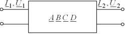
Figure 1 − Symmetrical four-pole
equivalent circuit of overhead line
Passive
four-pole is specified with generalized coefficients A, B, C, D which can be defined via line parameters [2]:
|
|
(1) |
 ,
,where ![]() − natural impedance of line;
− natural impedance of line; ![]() − propagation constant of electromagnetic mode in line; l – line length.
− propagation constant of electromagnetic mode in line; l – line length.
Relations between
natural parameters, generalized coefficients A, B, C and line
parameters can be got from equation (1) as:
|
|
(2) |
|
|
(3) |
III. Design procedure.
Fundamental
equations of four-pole wrote down respectively to the beginning and the end of
a line [4]:
|
|
(4) |
 ,
,where I1,
I2 -
vector current value, U1,
U2 -
vector voltages value at the beginning and the end of a line
correspondingly.
Formulas for the
determination of generalized coefficients A, B, C can be got from
the system of equations (4) under![]() :
:
|
|
(5) |
Current and voltage
vectors used in expressions (5) can be defined on the base of current (i1(tj), i2(tj)) and voltage (u1(tj), u2(tj)) instantaneous values
registered by Emergency Signal Recorders in prefault conditions at the beginning and the end of a line with using the generalized
vectors [5]:
|
|
(6) |
 ;
;  ,
,where
h1(tj),
H1, ![]() - instantaneous and absolute values of voltage or current
correspondingly;
- instantaneous and absolute values of voltage or current
correspondingly; ![]() - massif scale numbering,
- massif scale numbering,
![]() - signal cycle,
- signal cycle, ![]() – discretization interval.
– discretization interval.
Summing up the proposed method
of identifying line parameters includes following steps:
1) The respective vector values of currents and voltages are
identified by means of equations (6) on the base of current
(i1(tj), i2(tj)) and voltage (u1(tj), u2(tj)) instantaneous values
registered by Emergency Signal Recorders in prefault conditions;
2) Generalized
coefficients of two-port A, B, C are determined by formulas (5);
3) Natural
parameters of a line are calculated by equations (2);
4) Line
parameters are evaluated by means of
relations (3).
IV. Calculation example.
Described method of line
parameters definition was approbated by the example of 500 kV single-circuit
multiple-conductor overhead line, 600 km length. This line transmits power to
the load S = 600+j250
MVA. Reference dates of line parameters are presented in the Table 1.
Table 1 - Reference
dates of line parameters
|
L, km |
r0, Ohm/km |
x0, Ohm/km |
b0, 10-9 1/Ohm∙km |
g0, 10-6 1/Ohm∙km |
|
600 |
0,022 |
0,301 |
7,333 |
3,694 |
Firstly there
were calculated currents and voltages in the beginning
and the end of line by discretization interval ![]() =0,1 ms. Then there were
identified line parameters according to the method described
above. Calculation results are presented in the Table 2.
=0,1 ms. Then there were
identified line parameters according to the method described
above. Calculation results are presented in the Table 2.
Table 2 − Calculation results
|
A |
0,807+j0,014 |
|
B,
Ohm |
11,295+j168,747 |
|
C,
1/ Ohm |
-6,394·10-6+j2,072·10-3 |
|
D |
0,807+j0,014 |
|
Zv, Ohm |
285,544-j9,987 |
|
|
3,9·10-5+j1,055·10-3 |
|
r0, Ohm
/km |
0,022 |
|
x0, Ohm /km |
0,301 |
|
b0, 10-9 1/Ohm∙km |
7,333 |
|
g0, 10-6 1/Ohm∙km |
3,694 |
It can be
seen that defined line parameters correspond to their reference dates (Tables 1
and 2) and described method of defining line parameters is very correct.
V. Conclusion
1. Presented
method is applicable to stretched lines, as it takes into account dispersion of
line parameters by means of using fundamental equations for a long-distance
line;
2. The method
allows to identify real line parameters which can be used in fault location
identification algorithms decreased their errors;
3. The method
demonstrates high accuracy at defining of line parameters.
References
1. Mustafa Kizilcay,
Piergiovanni La Seta, Daniele Menniti, Michael Igel. A New Fault
Location Approach For Overhead HV Lines With Line Equations // Paper accepted
for presentation at 2003 IEEE Bologna Power Tech Conference. June 23th–26th.
Bologna. Italy.
2.
The research center «Bresler»
[An electronic resource]: Cheboksary,
2008-2011. URL: http://www.ic-bresler.ru/.
3.
Kulibin incorporated center of development of the Russian innovations [the
electronic resource]: working out modular high-precision reflectometer for
cable and overhead 2009. URL: http://
ru.domain1fc6c2.kulibin.org/.
4. Ryzhov Yu.
Long-distance ultra high voltage power transmission. – Moscow: MPEI publishing
house, 2007. – 488 p.
5. Method of
calculation of phase shift between two harmonical signals: pat. 2242014 Russia.
№
2003138149; decl. 31.03.03; publ. 10.12.04; bull.
№ 30.-
17 p.