INVESTIGATING SWITCHING OVERVOLTAGES IN THE ELECTRIC
EQUIPMENT OF THE OXYGEN-CONVERTER MANUFACTURES WITH THE HELP OF SIMULATION MODELS
Lipetsk state technical University
SHPIGANOVICH A.N., Prof., Dr. Sci. (Tech.), SHPIGANOVICH A.A, Assoc. Prof., Cand. Sci. (Tech.), Pushnitsa K.A, Asst., Cand. Sci. (Tech.)
For
investigation of switching overvoltages in the electric power supply system of
the oxygen-converter manufactures requires adequate simulation model, which
reflects the major processes that occur when triggering the switching device. Consider the main
features of this model. The main receivers of oxygen-converter
manufactures are induction motors of different power and complete transformer
substation (CTS) which feed on smaller receivers. Typical scheme will be power
supplied through intermediate distribution substations (DS), that is, the
scheme: transformer-line-DS-line-receiver, where the receiver performs an
asynchronous motor or CTS. Because the asynchronous motor has a much smaller
margin of dielectric strength of insulation than the transformer, then later it
was he who served as the research object. To build the models of elements we used Matlab package. The package
allows to model complex electric power systems, combining methods of simulation
and structural modeling. In constructing models of system elements into
account their active, inductive and capacitive resistance. For cable lines taken of their
distribution along the length of the line, and the dependence of the active
resistance of the frequency - the so-called skin effect. For the motor is additionally taken into account the
capacity between phases and between phase and earth, the attenuation in steel
at a frequency of free oscillations.The attenuation in the cable line and the motor
at high frequencies modeled connection in the appropriate
mode resistor whose value is chosen in proportion to the attenuation at the
frequency of free oscillations. General view of the model of the investigated system in Matlab package is shown in fig.1. Waveform processes, obtained on the model, are shown in fig.2,3.

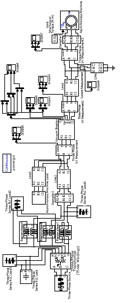

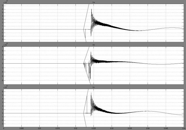
Fig.2. The
voltage on the switch (motor P = 100kW, cable L =25 m)
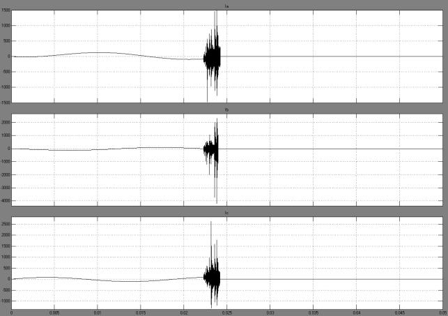
Fig.3. The current through the switch (motor P=100kW, cable L=25 m)
In
the simulation of the vacuum breaker take into account the following main provisions:
- dielectric
strength of a contact interval described by a linear dependence, and according
to [1] is 20-80 kV/ms;
- the growth of dielectric strength up to
the limit values occurs within 6 ms at a speed of 1 mm/ms [1];
- first
current interruption is possible in the case of instantaneous current value of not more than ic
(cutoff current, which depends on the contact material,
for modern switches is 2 - 5 A [1]);
- in case of the first and subsequent
breakdowns of contact interval is considered possible damping of the high-frequency current in its passage through the "zero" at a rate not higher than the
set (in the range of 50![]() 150A/ms
[1,2]);
150A/ms
[1,2]);
- arc resistance is taken into account
and simulated constant resistance.
Taking into account the above
provisions was built to simulate the model to
investigate the switching
overvoltages in the electric equipment of the oxygen-converter manufacture. Using
the model it was investigating the influence of different factors on the
process of overvoltages and offered protection schemes to reduce the
multiplicity of overvoltages, that allows you to build a rational system of
power supply in relation to protection against switching overvoltages.
REFERENCES
1. Evdokunin G.A, Tyler G.
Modern vacuum switching technology for medium voltage electric circuit (technical advantages
and performance
characteristics). St. Petersburg.: Publishing Sizov M.P, 2002.
148 p.
2. Kachesov V.E., Shevchenko
S.S., Borisov S.A. Overvoltages vacuum circuit breaker switching of motor loads
and monitoring // Overvoltages
limitation and neutral grounding electric circuit 6-35 kV: Proceedings
of the Third All-Russian Scientific and Technical Conference. Novosibirsk,
2004. P. 90 - 96.