UDK
631.18.004.82
A.A.Aulanbergenov
Kazakh
National Agrarian University, Almaty
Issues
of water supply and water drainage on private farm in Kazakhstan
Water supply and water drainage on private farm with livestock population up
to 100 heads of cattle needs establishing
production without wastes, on utilization of organic wastes and
livestock drains. The conducted
experimental researches on identification of the norms of water supply of the
cattle in Almaty region have shown that daily water consumption is qpac ==33…34
l/day, coefficients of hour and daily
unevenness are αr=2,13,
αday=1,07.
On water drainage norms we have obtained the following data:
Water
drainage for the cattle for cattle is
44…45 l/day, formation of hard drainage (moisture 73…76%)-6,9..72m3/day. Coefficients of hour and daily unevenness
are: λx=1,98 λday=1,2 λgen=2,3. The regime and
norms of water consumption of cattle have been studied, structural analysis of
sediment have been done and physical and chemical features of livestock drain
have been identified.
Chemical analyses of cattle drain have
showed the following: chloride content –3,3…5,2 mg/l, iron is missing;
magnium-421…546 mg/l; quantity of calcium has fluctuated in wide range; ammonia
nitrogen - 32,0…40,0 mg/m; BPC5 – 3200…4300 mg/l; BPCcomplete –4600…5660
mg/l; CPC-14700…15600 mg/l; weighed substances –17,9…18,7 g/l; common nitrogen-
1,3…1,4 g/l and hydrogen index PH-
8,06…8,07.
On bacterial analysis of cattle drain
we have obtained following data: colony calculation- 1,2…2,01-106 mln.; index number-more than 10 billiards;
pathogenic flora is missing. General analysis shows that indices of VPC, HPC,
phosphorus and potassium are slightly high. Before using such drain for
irrigation it is necessary to make the required norm of concentration of
elements of content of the drain by
means of processing using method of anaerobial fermentation on special devices.
Processed drain meets environmental
requirements, eliminates infection of people and animals with disease agents,
soil, ground water and plants
overloading with harmful substances and microorganisms. Simultaneously
we can obtain low cost fuel such as biogas consisting of methane (65…70%),
carbonic acid gas (27…32%) and hydrogen sulphide (up to 3%). Energy contained
in 30 m3 of biogas is equal to the energy of 18 m3 of
natural gas, 22 liters of oil, 20 liters of diesel.
World energy and environmental crisis
of 70th of XX century has preconditioned wide development of biogas
technology in USA, Germany, England, France, Italy, Finland, China, India and
other countries. At present period in China there are more than 5 millions and in India more than million of biogas
devices with reactor volume of 8-10 m3, that provide more than 50
min. farmers with gaseous fuel .
In the US biogas covers
1,6% of energy consumption in agriculture and in India it covers more than 20%.
In general the development and implementation of small capacity biogas device
on farms in the republic will provide solution of energetic and economic
problems in rural places.
Therefore in choosing and development
of technological scheme of complex biogas system it is necessary:
-
to chop manure and other organic wastes to the
size of not more than 0,005 m and maintain content of moisture in the initial
substance on the level 88-90%;
-
during device launching the filling should be done within 5…30% of
the whole loading volume. Fermentation process should be thermophil (50-550).
It includes two phases. In the first phase up to 350C the process
takes place quickly, then in the second phase after 4-6 days temperature is
increased up to working temperature to
10C per day;
-
daily loading dose of working chamber of
bioreactor (methantenka) during heating period from 35 to 500 C
should be accepted as 10% and in the set regime-18-30% from loading volume.
Mixing of fermented substance should be done with the help of vacuum tower
every 5-6 hours 3-4 times;
-
for improving fermentation process of liquid
drain, 0,1% of carbon oxide should be added;
-
systematic control the quantity of pathogenic
microorganisms and viable helmint eggs in manure after fermentation.
Based on the requirements of the
proposed technological process of fermentation
of farm drain we have developed various schemes of bio energy devices.
Construction of experimental bio energy device is shown on picture.
Liquid organic wastes and
manure drains on farm are taken to the
reservoir of 1 preparation of fermented manure and are kept there until needed
consistency, catalyser of sediment
fermentation process is added. Reservoir of preparation is covered with
damper 2 providing cycle loading of device with fermented material. Delivery of
prepared manure drains is done with the help of re-circulation pump 3, equipped
with homogenisator made as hydro monitor cone nozzles and is located on
loading-overflow hatch 5, with consideration of the most effective use of
stream energy. Bioreactor (methane
device) 6 is situated horizontally with
bottom decline 0,01-0,020 to
the loading-overflow hatch.
To conduct
montage, maintenance and repair-exploitation works the bioreactor is equipped
with technologic hatch with diameter 0,6 m situated in its upper part. Filling
level of bioreactor with drains and process of
their barbotage are controlled
with the help of vision window 8 situated up the calculation loading level. For
providing continuous fermentation
process in loading-overflow hatch the bolt
9 works for draining of the
changing quantity of thrown sediment.
To maintain optimal temperature for viability of mizophyl methane
bacteria in bio-reactor the system of electric heating is used that consists of
electrode water heater 10 type EVM, tubular heat exchanger 11
situated inside bio-reactor, extending tank 12 and pipe line armature
13. For throwing output biogas (methane) the system of pumping out and storage
is foreseen including piston compressor
14 and receiver 15 with 1 m3 volume.
Research results show that the
assumed bioenergy device provides automation of technological process of bio gas production and obtaining of
qualitative organic fertilizer.
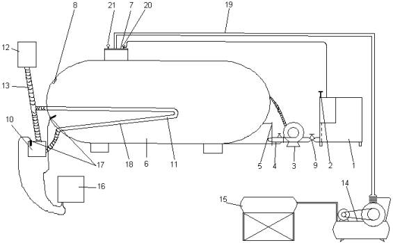
Pic. Principal scheme of
experimental bio energy device.
1-reservoir of
drain preparation; 2- damper; 3-
re-circulation pump; 4-hydromonitor device; 5- loading-overflow hatch;
6-bio-reactor; 7- technological hatch; 8- vision window; 9- bolt; 10 –electrode
heater; 11- tubular heat exchange; 12- extending tank; 13- pipe line armature; 14- compressor; 15-
receiver; 16-mangement box; 17- TSM sensors.
Publications:
1. A.Sasson. Biotechnology. M.: Mir,-1982
2. V. Baader and others. Biogas (theory and practice). M., Kolos,-1982