S. N. Fedosov, T. A. Revenyuk
Department of Physics, Odessa National Academy of Food Technologies,
Odessa, Ukraine
INCREASING
INFORMATIVITY OF THE THERMALLY
STIMULATED
DEPOLARIZATION METHOD
Two modifications
of the Thermally Stimulated Depolarization Current method are proposed to
improve resolution and sensitivity of the method by connecting either a real
capacitor, or an additional resistor in series with the sample. It is shown
experimentally that high sensitivity of the TSDC method with an air gap can be
obtained, if the gap is substituted by the capacitor, while all advantages of
the method remain in force. It has been found that in one experiment it is possible
not only to measure the TSD current, but also to obtain data on the Thermally
Stimulated Conductivity, if the properly selected additional resistor is
periodically switched on and off.
INTRODUCTION
Thermally
stimulated depolarization current measurement is one of the important methods for
identifying and characterizing relaxation processes in electrified dielectrics
and electrets [1,2]. At the same time, the most commonly used modification of
the method with two short-circuited electrodes attached to the sample has some
disadvantages and drawbacks. In particular, depolarization currents caused by
relaxation of homo- and heterocharge flow in one direction making difficult
separation and characterization of the components. Moreover, it is very probable
that the intrinsic resistance of the sample in the high temperature part of the
experiment becomes comparable, or even smaller than that of the measuring
device. As the result, the real TSD current is distorted and even stray
currents are often observed. In this paper we suggest two modification of the
TSDC method free of the above-mentioned drawbacks.
In order to make
homo- and heterocharge relaxation currents flow in opposite directions, a modification
of the TSDC method has been proposeed with an air gap introduced between the sample
surface and one of the electrodes [3]. It has been proved that the air gap must
be as narrow as possible to provide for the reasonable sensitivity and in any case
to be much smaller than the thickness of the sample. However, in the case of
thin polymer electrets having thickness from about 10 to 30 μm, it is difficult to realize and maintain such an air gap. That is why,
the air gap is sometimes replaced by a thin non-polar dielectric spacer, for
example a Teflon film inserted between the sample and the electrode [2,3]. In
this work we suggest a much better solution for improving resolution and
sensitivity of the TSDC method.
REAL CAPACITOR REPLACES
THE DIELECTRIC GAP
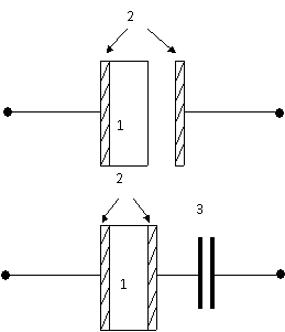
From electrical
point of view, the gap between the
electrode and the sample or the spacer
works as a capacitor C connected in
series with the sample (Fig. 1). Hence, the expression for the
depolarization current through the
gap can be written as
![]() (1)
(1)
with ![]() , (2)
, (2)
where U is the gap voltage that
changes as the result of the charge accumulation at the gap boundaries, εo
the permittivity of a vacuum, ε the dielectric constant of the spacer ε=1
in the case of is clear from Eqs. (1) and (2) that the gap must be as narrow as
possible to obtain reasonable sensitivity of the method.
Assuming that
thickness of the Teflon film spacer is 10 μm, the dielectric constant of
the
spacer e=2,3 and the surface area
A=1 cm2, one obtains C =200 pF, which is not enough to guarantee high
sensitivity for the sample thickness in the range from 10 to 30 μm. From
the other side, it is impractical to use a thinner spacer because of the
breakdown problems.
![]()
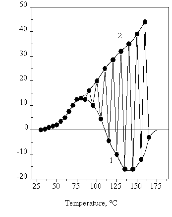
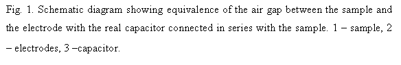
Fig. 2. Temperature dependence of the current
during the TSD experiment with the two-side electroded PVDF-PZT composite
sample. The series capacitor of 0.1 μF is periodically switched on (1)
and off (2). The heating rate 3 K/min, the sample thickness 560 μm.
We have found
experimentally that good results can be obtained, if the air gap or the dielectric
spacer is replaced by a real capacitor, provided that its capacitance is much higher
than that of the sample. In this case,
the considerable increase in sensitivity is observed comparable with the
sensitivity in TSDC experiments with non-blocking short-circuited electrodes.
This is confirmed
by the data in Fig. 2 showing the TSD current while the capacitor
connected in series with the sample
is periodically switched on and off. It is seen from Fig. 2 that at the initial
stage the same TSD current is observed with and without the capacitor.
Calculations show that in order to obtain the same sensitivity with a dielectric
gap, its thickness must be of the order of 0.02 μm (assuming e=2.3) that
cannot be practically realized.
With increase of
temperature, as follows from Fig. 2, the difference between the TSD current
with and without the capacitor increases, while, according to the theoretical
model, the current at the end of the depolarization process should decrease to
zero in both cases. Abrupt current increase in short-circuited samples is
probably caused not by the relaxation process, but is rather a result of stray
EMFs that under increased conductivity induce large parasitic currents. The suppression
of the stray currents is 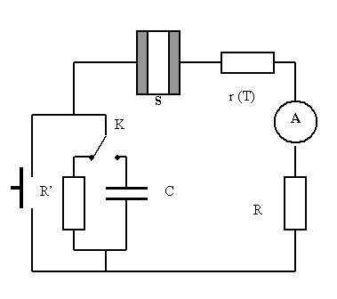 one of the basic advantages of the proposed method.
Thus, by
periodically switching the series capacitor on and off, one can obtain in one experiment
the two TSDC curves corresponded to the short-circuited mode and the mode with
the dielectric gap. By comparing the two curves, one can make conclusions on
the nature of relaxation processes and calculate their parameters. For example,
from the data presented in Fig. 2 it is clear that there are two relaxation
processes in PVDF-PZT composites related to homo- and heterocharge. It is seen
that the homocharge is more stable than the heterocharge. Besides, there are non-compensated
stray EMFs in the experimental setup causes most probably by potential differences
between contacting metals.
We took
polymer-ceramics composites here only as an example for showing applicability
of the proposed modification of the TSD current method. We also examined the
method on pure polymer electrets, such as uniaxially stretched PVDF films of 25
μm thickness, and non-linear optical polymer films of polystyrene doped
with DR1 chromophore and poled in a corona triode.
ADDITIONAL RESISTOR IN
SERIES WITH THE SAMPLE
It is known that
during the measurement of a current, the intrinsic resistance of the current source
r must be much larger that the input resistance R of the ammeter (r>>R),
otherwise, due to redistribution of voltage between the sample and the ammeter,
reading of the meter would not correspond to the real value of the current.
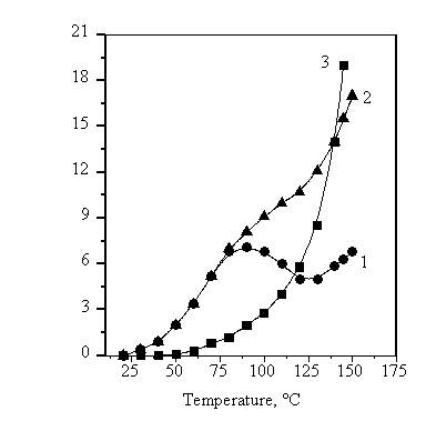
Fig. 4. TSD current curves for a charged composite
PVDF-PZT obtained with the additional resistor of 220 MO that was
periodically switched on (1) and off (2). Also shown is the temperature
dependence of conductivity (3) derived from the curves (1) and (2). The
electret was formed at T=100°C, E=12 MV/m during t= 0.5 h.
![]()
In the case of
the TSD current measurements, the resistance of the meter remains constant, while
that of the sample decreases with time and temperature. Thus even if the
condition r(T)>>R initially is met, it might be destroyed in the high
temperature region and the current shown by the meter would become larger than
the real depolarization current. Moreover, stray currents will not be limited
any more by the resistance of the sample, so the meter will show continuously
increasing current, while the real depolarization current should go to zero at
the end of the depolarization experiment.
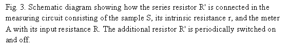
To avoid the
complications, we propose to connect an additional resistor R' in series with
the sample (Fig. 3). The value of the resistor R' is selected in such a way
that it should be much smaller than the resistance of the sample r in the low
temperature range of the TSDC experiment, while to be much larger than the
latter in the high temperature range, i.e. it should satisfy the following conditions
R'<<r(T) at low
temperatures,
R'>>r(T) at
high temperatures. (3)
If the above
conditions are met, the TSD current will not be distorted in either temperature
range. As one can see from Fig. 4, the TSD current in the low temperature part
with the additional resistor is the same as the current without the resistor,
indicating that R' can be neglected at low temperatures comparing to r(T). In
the high temperature part of the experiment the current with the additional
resistor becomes much more relief than without the resistor, with relaxation
peaks clearly distinguishable, because now R' "substitutes" r(T) that
drastically decreases with temperature, while the stray currents are also
suppressed. We have found one important feature of the suggested mode of the
TSD current measurements. By periodic switching on and shortening the
additional resistor R' one can obtain two TSD curves, from which the
temperature dependence of the intrinsic specific conductivity g(T) of the
sample can be easily obtained. Simple calculations based on the schematic
diagram shown in Fig. 3 gives the following expression
![]() (4)
(4)
where I(T) is the TSD current without the additional resistor R', I'(T) the current with the resistor R', d
the sample thickness, S the surface
area of the sample.
All three curves
– two experimental ones and one calculated – are shown in Fig. 4. As one can
see, the temperature dependence of conductivity shows a typical exponential
behavior.
CONCLUSION
Two methods for
improving informativity of the TSD current measurements are proposed and its
application is illustrated. In the first one, an additional capacitor is
connected in series with the sample resembling the TSD mode with the air gad or
the dielectric spacer, but with much higher sensitivity and with suppression of
the stray currents. In the second method, a properly selected resistor is
connected in series with the sample and the ammeter. In this case, if the
additional resistor is switched on and short circuited during the TSD
experiment, one obtains information as if the two thermally stimulated methods
are combined in one experiment, namely the TSD current measurement and the TS
conductivity measurement, since one gets simultaneously data on both the TSD
current and the thermally stimulated conductivity (TSC). It is important that
the measurement of the conductivity is performed without any external power supply,
but rather under internal self-balanced electric field. In this case, the
higher resolution power is expected in comparison with the traditional method.
REFERENCES
[1] V. Sangawar, C. S. Adgaonkar
Dielectric behavior of undoped and doped PS thermo-electrets // J Polym.
Mater., v. 13. - № 3. - P. 207-210 (1996).
[2] J. van Turnhout, Thermally
Stimulated Discharge of Polymer Electrets, Amsterdam–Oxford–
New York: Elsevier, I975.
[3] G. M. Sessler (ed.) Electrets,
Vol. 1, Third Edition, Laplacian Press, Morgan Hill, 1999.