RESEARCH AND ORGANIZATION OF DIRECTED air flow in
centrifugal mixer
Borodulin D.M. 1, Sukhorukov D.V. 2
1
Kemerovo Institute of Food Science and Technology
2
Kemerovo Institute of Food Science and Technology
Russian Federation
The organization of the mixing process at the
present time is one of the priorities
of the decision which will significantly improve the quality of the
product and, thus, greatly reduce
the cost of its production. In the centrifugal mixers
organization forward and backward
movement brings the material flow structure of the movement
blend components to the model of ideal mixing.
In some designs of centrifugal mixer this method is
realized by direct particles
flows through the
bypass holes and windows formed on the conical surface
of the rotor and in the opposite direction through the
installation of various apparatus
in the form of
reflectors. They can be designed
as separate elements of the torus,
of identical size and installed in a staggered on different cones of the
edges smaller bases in the form of solid rings
and the rings with the holes
[1]. Common disadvantage of centrifugal continuous mixers (CCM) is that the
centrifugal force component in a highly
dispersed rise up. The result is
a partial bundle (segregation).
Currently, the leading scientists in the
field of mixing actually studied the effect of air currents on the quality of the mix,
but the more highly dispersed components that go into the airspace above the rotor mixer. Therefore, investigation of the direction and speed of air flow in the interior of the centrifugal continuous mixer is an actual
scientific problem of interest to many industries.
In operation, centrifugal mixers highspeed rotor by
centrifugal force, an air flow in
the movement of fine particles which are
involved components. The
resulting air currents affect the
structure of the material flow, moving
along the surface of the cones. This is reflected in the work of the entire apparatus. Thus, there is
a need to determine the nature and parameters of the air flow formed in the workspace mixer for further organization
of their direction of movement.
By rotating the cone of the rotor boundary layer of
air starts to move , due to friction . This layer moves away from the rotor
center to the periphery under the action of inertia forces . Air velocity can
be decomposed into three components : a peripheral Wp - tangential to the
surface of the rotor in the direction of its rotation , radial Wr - directed
from the center to the periphery of the rotor and an axial Wa - acting in the
vertical direction from the base of the rotor up. Thin radial movement of air
flow occurs in the vicinity of work surfaces mixer , such as a rotor housing
cover . Left airspace bounded work surfaces CCM rotates together with the rotor
with a slightly lower speed . Axial movement of the air flow occurs in the
direction perpendicular to the base of the rotor.
Constituent airflow will depend largely on the size of
CCM , rotor structure and its frequency of rotation. In our experimental
studies to determine the values of the velocity of
airflow was used centrifugal mixer [ 2], the rotor is made in
such a way that it could install different versions of the cone ( Fig. 1).
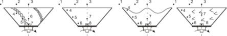
a b c d
a) smooth
cone with blades;
b) smooth
cone;
c) a
smooth cone with a wavy top edge;
d) a
smooth cone with angled vortex generators.
Fig. 1 Modifications of
cones
During the experimental studies, we used the following procedure.
The components of the air velocity was measured
at idle at various points and destinations within the rotor mixer. Measurements of air
velocity was carried out by a
microprocessor hot-wire anemometer-thermometer TTM-2.
For experimental studies on the rotor of a centrifugal
mixer alternately installed one of the versions
of the cones (Fig. 1). The measurements were performed at frequencies of rotation of the rotor 10 s-1 and
24 s-1.
From these results we can make the
following conclusions.
The axial velocity component. As the rotor
rotates with a frequency of 10
s-1 achieved its maximum value on a smooth cone with angled
vortex generators. It is more than 20%, 2% and 10%,
respectively, relative to Wa measured on modifications (a), (b) and (c). As
the rotor rotates with a frequency of 24 s-1 achieved its maximum value Wa achieved using modifications of the cone (d). Its speed is more than 12%, 8% and 7% with
respect to Wa measured on modifications (a), (b) and (c).
The radial component of velocity.As
the rotor rotates with a frequency of 10 s-1 to
smooth the air flow from the angled turbulators cone over 3% , 1 % and 17 % ,
measured by than Wr modifications (a), (b) and (c) . As the rotor rotates at 24
s-1 Wr reaches a maximum value on a smooth cone with angled vortex
generators . It is more than 20 %, 13 % and 16 % with respect to air flow
velocity in the radial direction of the cone modifications (a ), (b ) and (c )
respectively.
The circumferential velocity component in the range 1
.. 0.4 m/s is observed partial involvement of fine components in the air space
of the working chamber of the centrifugal mixer. Further increase Wp to 3.5 m/s
results in a swirling flow motion dusty and hence to the appearance of the
resulting mixture segregation process . This results in reduced efficiency of
mixing. The strong pattern is observed on a modification of the rotor in the
form of a smooth cone with throughputs windows and blades. Since the latter
provide additional ventilation effect, which leads to additional turbulence in
dusty threads, so to eliminate segregation and increase the efficiency of
mixing , an apparatus inside the mixer guide or reflective elements allow you
to specify the desired direction of air flow.
According to the results of experimental studies have
made the following conclusions.
We determined direction and velocity of air flow at
various points in the processing chamber of a centrifugal mixer with different
speeds and designs cone. When the values of
the circumferential velocity component in the range 0,4 ÷ 1 m/s, there
is a partial engagement of fine components in the air space over the working
chamber . Further increasing it to 3.5 m/s leads to a tangential movement dusty
flows (with particle diameters of 80 ÷ 120 mm) above the rotor and the
occurrence of CCM segregation process, which reduces the efficiency of mixing.
The strong pattern is observed on a modification of the rotor in the form of a
cone with an angled vortex generators that create additional ventilation effect
that enhances the speed of dusty flows. Therefore, its elimination and
increased mixing efficiency is advisable to install rails or reflective
elements, the direction of fine components contributing to the base rotor.
The experimental results showed that the lowest values
of the velocity of air flow falls on the center of the rotor. It was
established experimentally that in the center of the rotor is formed stagnant
zone. To eliminate it, we asked: do the base of the rotor in the form of a disk
with concentric hollow cone mounted facing up top, set over a cone axial fan
[3] or a reflector with a toroidal surface [4]. These designs allow you to
organize the directed movement of highly dispersed dust particle flows of
material in the chamber new faucets and increase the quality of the resulting
mixture at 2,5 ÷ 4,3%.
List of literature used
1. Borodulin
D.M. The development of centrifugal mixing equipment for dry and wet combined products: monograph / D.M. Borodulin, V.N.
Ivanec. - Kemerovo, 2012. - 178 p.
2. RF
Patent RU 104867, Russia IPC V01F 5/22, 2011.
3. RF
Patent RU 2216394, Russia V01F IPC 7/26, 2003.
4. RF
Patent RU 2200055, Russia V01F IPC 7/26, 2003.