Технические
науки/ Авиация и
космонавтика
Nickolay Zosimovych
National Aviation University,
Kyiv, Ukraine
SIMULATION OF THE
INTEGRATED ONBOARD SYSTEM FOR A
COMMERCIAL LAUNCH VEHICLE
In the article has
been chosen and modeled integrated guidance system of a commercial launch
vehicle with application of GPS technologies. Under researching was developed process
of simulation of the dynamics of the spacecraft constellation, providing the
process of functioning integrated navigation system of the launch vehicle by
using object-oriented
approach.
Keywords: Guidance, Launch Vehicle (LV), Onboard Integrated
Control System (OICS), Inertial Navigation System (INS), Global Positioning System (GSP), gyro,
satellite, constellation, Gravitational Potential of the Earth (GPE), Sun, Moon,
pseudorange, pseudovelocity, object-oriented approach (OOA).
I. Introduction. In this study we shall consider a concept of integrated onboard systems for launch vehicles in the context of the current task, and provide mathematical models of all its elements for different variants of their structure and composition.
Integrated onboard guidance and navigation systems
used in launch vehicles allow applying modern information technologies most
appropriately to ensure the required quality (accuracy and reliability) of
navigation [1-3]. The analysis shows that the onboard integrated control
systems (OICS) have a number of features, main among them being unification of
respective functional groups on the level of technical solutions [4, 5]. For example,
all processor sections of a computer system are the same, irrespective of the
problem they solve: navigation, guidance or stabilization. This fact makes away
with one of the main disadvantages of the traditional (composite) on-board
control system – excess range of schematic and technical solutions [6].
Unification of schematic and technical solutions by minimizing their number and the
number of hardware components results in higher system reliability, reduction in
the number of control and of technological equipment, cutting of development
time and, ultimately, reduction in the cost of both the system as a whole, and
the process of its design [2].
It is known that the algorithm of inertial
navigation system is based upon
integration of acceleration values of the launch
vehicle sent by integrating accelerometers
and reconstruction based upon
calculation of the apparent way of its full position and
the velocity in the coordinate system used to solve
the navigation task by taking into
account accelerations caused by
the gravitational influence of the Earth
[3, 4, 7, 8].
II. Problem setting. The process of conceptual design of
the onboard integrated system for a commercial launch vehicle includes in
particular synthesis of navigation and control algorithms. In its turn, the
synthesis may be successfully implemented only if there are appropriate
adequate models of motion of the object, permanent (predetermined) elements of
control and navigation system (control actuators, gyroplatform or SINS, GPS receiver, etc.), as well as models of steering and
disturbance forces and moments influencing the launch vehicle in flight.
It is obvious, that viability and efficiency of
the synthesized algorithms and the adequacy of the respective models can be
described in details in the present research only by imitation mathematical
simulation of the process of controlled motion of the launch vehicle taking
into account the whole range of steering forces and moments.
Such simulation suggests creating sets of
motion and disturbance models. The first of such sets shall make a so-called
model of “external environment”, and the components making the model are most
explicit and exact. This refers primarily to simulation of the center of mass of
LV, as well as to disturbance models. All the named models have already been
described earlier [3, 8]. Here we shall only remind that in the process of
creation of a “real” trajectory of LV chance factors such as divergence of
initial launch conditions, error in the assembly of the stages of the launch
vehicle (turn and misalignment of stages in reference to their target
position), thrust deviation from the vector rated in size and directionally,
variations in atmospheric density, drift and trend of output signals of
gyroblocks and accelerometers, errors in tailoring of pseudo ranges and pseudo
velocities owing to onboard clock bias and zenithal errors (tropospheric and
ionospheric refraction), errors of actuating mechanisms will be taken into
consideration as well. Non-sphericity and anomalies of Earth's gravitational
field were considered as a determining disturbing influence.
We shall point out that such formulation of a guidance
task is naturally simplified as much as possible, and doesn’t allow, in
particular, to study the process of injecting a payload into the Earth orbit,
because this process supposes manoever of the final stage, and consequently
solving on board a respective boundary task in one form or another. But, as it
has been many times emphasized [1, 3, 4,
7, 8], the purpose of the present research is to formulate efficient and
precise navigation algorithms, based on the use of SINS and the GPS - receiver.
In connection with the foregoing,
it is obvious that high precision
solution of a navigation task will allow to implement manoevers needed to launch a payload, all other conditions being
equal.
III. Results and Discussion. Statement of a simulation task may be illustrated using a functional scheme
[8], which suggests creation of an instrument, namely a program complex
designed to implement tasks and objectives of research.
The most appropriate and suitable for the creation of such a complex is object-oriented approach
(OOA). This approach makes it possible to develop a flexible and extensible Methodological Software of the required level
of complexity, allowing to use
hierarchical structures of inherited classes in the form
of appropriate libraries, and to ensure security of
stored data [9].
It must be noted that while using OOA, we have to determine the so-called
processes and the structure of the
corresponding hierarchy of these classes
[9]. This type of research
is very poorly formalized,
but, nevertheless, based on existing
experience we can make the following recommendations for development of an object-
oriented scheme of software and
mathware:
1.
All
the material objects of research, such as aircraft, control systems, power
meters, etc., which are the systems with a finite number of inputs and outputs
must be a "black box" with a number of properties, but with a hidden
mechanism of functioning.
2.
It is advisable to start building up a hierarchical chain of
such classes with the most general, abstract class, where only the most general fields, typical for the whole
intended chain, are identified, and
where methods are declared as virtual
and abstract ones. In other words,
in such classes only field structures
and template methods are declared, and
the method bodies themselves are absent. This
requires overlapping
them in descendant classes.
3.
If complex algorithms requiring a large number of settings and additional procedures are used during the
simulation, it is necessary to build up
libraries for the correspondent classes that shall implement the mentioned algorithms.
In such a case, the method which specifies the initial mathematical
problem must be declared abstract
to further overlap in the descendant within the present project
(for example, the function of calculation of the right sides of the system of ordinary
differential equations).
4.
It is advisable that auxiliary procedures and simple algorithms should take the forms of individual modules without ascribing them to any class in order to simplify the overall structure and, as noted above,
to improve the performance of the
program. For example, the best thing is to collect the
functions and procedures of matrix
algebra, algebra of complex numbers, quaternions,
tensors, etc. in separate
modules, having previously described respective types (matrix,
complex number, quaternion, tensor etc.).
5.
If the studied processes are characterized by nesting, i.e. one process
is connected directly or
indirectly with several others, the class that implements this process must
provide the appropriate field for the object from the class, which
implements the nesting process.
It should be noted that such nested objects are to be created from the outside, i.e. in
the calling program with transmission of the created objects into the
addressed classes. It is necessary
to ensure that the different classes
use only one instance of this class, and access
to its data is coordinated.
Thus, during the initialization of the whole structure, most independent
simple objects must be created first,
and thereafter complex composite objects
are to be made.
Thus, considering the above, we may present the
architecture of a software complex that implements the functional diagram [8].
This architecture is shown in Fig. 1. Because when creating a software system,
you should be guided by the requirements in respect of the efficient use of
computing resources, as well as by the requirements regarding accuracy and
speed of calculations.
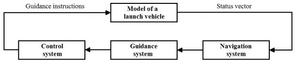
Fig. 1. Architecture of a software complex
Let’s consider each of the elements of the
functional diagram in order to determine the composition and functional purpose
of the classes, which determine object structure of software and mathware in
compliance with OOA.
The LV Model Block describes the dynamics of LV
(as the center of mass (CM) and angular motion) influenced by forces and
moments conditioned by the environment and deflection of controls. In order to
determine basic classes and the corresponding chains of descendant classes
implementing the element under consideration, we shall specify the required
models and algorithms implementing the process of simulation of the LV dynamics
with indication of the required initial data.
In its core, the problem in question is the
task of integrating the system of ordinary differential equations (ODE) of the
first order.
Thus, in the context of software
implementation, the block contains two classes: a class that implements the
numerical method of integration of ODE systems, and the class describing a
model of forces and moments of uncontrolled motion of the CM and the angular
motion of the LV.
Let’s consider the chain of classes implementing
the library of methods of numerical integration of ODE systems (Fig. 2).
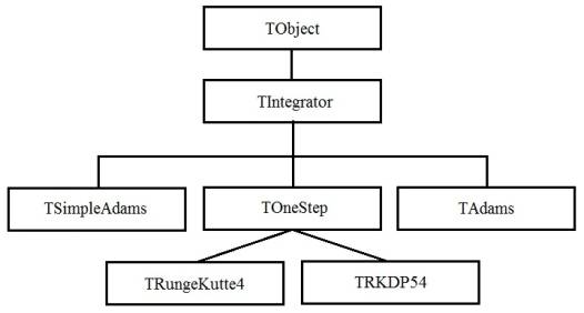
Fig. 2. Library of the
methods of numerical integration of the systems of ordinary differential
equations
The library contains the following methods:
· Runge-Kutte methode;
· the nested Dormand-Prince method;
· Adam-Bashforth-Moulton predictor-corrector method.
All the methods accept the nested one, have a constant integration step
and lacks evaluation of local error at each step. The predictor-corrector
method is an iterative one, and completion of iterations is determined either
upon achievement of a given accuracy of residual error in the two last solutions,
or upon achievement of a specified number of iterations.
To solve the problem of simulation of the LV dynamics we will use the nested
Dormand-Prince method of the Runge-Kutte family [10], and to solve the basic
navigation equation for INS, the predictor-corrector method will be used.
The full vector of the dynamic system status includes
components of position, velocity of the LV in the ideal navigation coordinate
system INCS, the quaternion components and output signals from drives of
control motors of the LV. At the same time, we shall note that due to the
discrete nature of the control loop (frequency 64 Hz), control signals are
assumed to be constant during one cycle of the system controlling the operation
of control engines.
The
numerical integration methods themselves are described in detail in [74], and
the peculiarities of the implementation of these methods regarding salvation of
aerospace tasks are described in [11].
Simulation Results and their Analysis. The Fig. 3-4 show average to
implementation deviations of the position and velocity of the LV in the ideal
navigation coordinate system estimated with application of the strapdown
inertial navigation system (SINS) [12, 13].
|
|
|
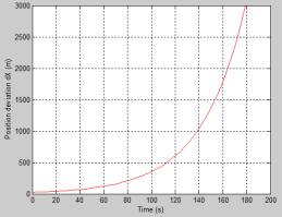
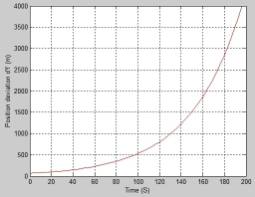
Fig. 3. Deviation of the X,Y-coordinates
|
|
|
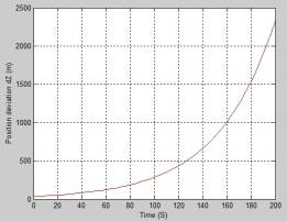
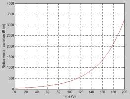
Fig. 4. Deviations of the Z-coordinate and the radius-vector R
IV. Conclusions.
1. Offered a concept of the integrated
navigation system for the commercial launch vehicle using GPS technologies.
2. Developed a system of models and
algorithms providing both modeling of the process of functioning of the
integrated navigation system and function simulation of the onboard navigation
system of the launch vehicle itself.
3. The system includes:
1)
a model
of controlled motion of the center of mass
within 3 stages of the launch vehicle
and relative to the center of mass, taking into account non-centrality of the
gravitational field, variations in the density of the atmosphere, wind gusts, thrust distribution, assembly errors and thrust errors;
2)
algorithms
for solving navigation tasks using GSP, OINS and GPS data;
4. The number of errors in determining
position and velocity of a launch vehicle reduce in rigidly bound systems using
a strapdown inertial navigation system and a GPS receiver (error along the
radius vector is ![]() m and the
absolute velocity is
m and the
absolute velocity is ![]()
![]()
References
1. Nickolay
Zosimovych, Anatoly Voytsytskyy. Design objectives for a commercial launch
vehicle with integrated guidance system. Novus International Journal of
Engineering&Technology, Vol. 3, No 4, 2014, PP.7-28.
2. Nickolay
Zosimovych, Anatoly Voytsytskyy. Disturbed Motion of the Launch Vehicle with
Integrated GPS/INS Navigation Systems. "Бъдещите изследвания – 2014" Proc. X International
Scientific and Practical Conference, Sofia, 17-25 February, Vol. 49. Technologies. Physics, Sofia: Бял ГРАД-БГ, 2014, PP. 3-9.
3. Nickolay
Zosimovych. Integrated Guidance System of a Commercial Launch Vehicle. "Modern European Science – 2014" Proc. X International
Scientific and Practical Conference, Sheffield, 30 June – 7 July, 2014, Volume 18. Technical sciences, Science and education LTD, 2014.
- PP. 10-22. ISSN 978-966-8736-05-6, Registrated Number:
08878342.
4. Zosimovych
Nickolay. Selecting Design Objectives for an Integrated Guidance System of a
Commercial Launch Vehicle with Application of GPS Technologies. The Open Aerospace Engineering Journal, 2013,
Vol. 6, PP. 6-19.
5. Jiann-Woei
Jang, Abran Alaniz, Robert Hall, Nazareth Bedrossian, Charles Hall, Mark Jackson.
Design of Launch Vehicle Flight Control Systems Using Ascent Vehicle Stability
Analysis Tool. AIAA Guidance, Navigation, and Control Conference, 08-11 August
2011, Portland, Oregon, USA, AIAA 2011-6652.
6. Nail F. Palumbo,
Brian E. Reardon, and Ross A. Blawkamp. Integrated Guidance and Control for Homing Missiles. Johns Hopkins APL
Technikal Digest, Vol. 25, №2, 2004,
pp. 121-139.
7. Nickolay
Zosimovych. Modeling the Integrated Guidance System of a Commercial Launch Vehicle, International
Refereed Journal of Engineering and Science (IRJES), Volume 3, Issue 6, June
2014, PP. 39-54.
8. Nickolay
Zosimovych, Functional Simulation of the Integrated Onboard System for a
Commercial Launch Vehicle, International Refereed Journal of Engineering and
Science (IRJES), Volume 3, Issue 11, November, 2014, PP.92-106, ISSN (Online)
2319-183X.
9. Шлеер С., Меллор С. Объектно-ориентированный
анализ: моделирование мира в состояниях: Пер. с англ. — Киев: Диалектика, 1993,
240 с: ил.
10. Alfio
Quarteroni, Alberto Valli. Numerical Approximation of partial Differential
Equations. Springler Series in Computational Mathematics, 1991.
11. Кудряшов С.В. Основы статистической динамики
комплексных информационных систем, М.: МАИ, 2003.
12. Nickolay
Zosimovych, A Model of Dynamics of a Constellation of Navigation
Satellites. Nauka i
studia, № 3 (134), 2015, PP. 51-58, ISSN 1561-6894.
13. Nickolay
Zosimovych, Model of Inertial Navigation System with Integration Schemes for a
Commercial Launch Vehicle. International Journal of Engineering
Technology&Advanced Engineering (IJETAE), Vol. 5, Issue 2, February, 2015,
PP. 479-485, ISSN 2250-2459, ISO 9001:2008 Certified Journal.