Lyubimov v. v.
Pushkov institute of terrestrial
magnetism, ionosphere and radio wave propagation (IZMIRAN) Russian
Academy of Sciences
TEST RESULTS OF DIFFERENT ELECTROMETRIC VARIOMETER SENSORS
I. INTRODUCTION
The existence of the electric field (EF) in the Earth's atmosphere is mainly
due to the processes of air ionization and spatial separation of the ionization
occurs when positive and negative electric charges. EF, in spite of the
complexity of the systems and conditions of their registration, are considered
in geophysics as one of the main physical factors of the processes occurring in
the surface layer.
From [1-3, 9] show that variation of the EF surface
layer caused by geophysical processes may experience changes up to orders of
magnitude above the background. Many atmospheric processes such as solar
activity, convection and formation of clouds, precipitation, lightning
discharges cause partial separation of opposite charges and the emergence of
atmospheric EF, with respect to the atmosphere surface of the earth is charged
negatively. Existence EF the atmosphere causes currents, discharge electric
"condenser" atmosphere - surface of the Earth.
In recent years more and more attention of researchers
attracts the problem of the impact on the environment geophysical factors [9],
has created quite a lot of different methods and unique instrumentation for the
measurement of EF, some of which are presented in [1-12]. It was important to
research the electrical characteristics of the atmospheric boundary layer,
where flows a large part of human activity. Changes EF here come under the
influence of various anthropogenic and natural processes. Therefore, the main
objective of the research is the monitoring of the EF surface layer of the
atmosphere with the impact of anthropogenic processes on the natural EF.
Improvement of techniques for the study of EF surface
layer of the atmosphere is currently pressing problem for researchers and
practitioners, including the creation of new methods and devices for monitoring
atmospheric EF. An important task is the creation, for example - ROSGIDROMET
(methods RD52.04.567-96 and RD52.04.168-2001) [8], a measurement network spaced
stations equipped with modern instruments capable of operating in all weather
conditions.
Described in this article work is proactive and is
based on the results of long-term stationary measurements of EF in the
atmospheric surface layer carried out on the territory of IZMIRAN at spaced
measuring points (MP) for small
measuring range. At the same time, the ideology of the whole work was aimed at
the creation of new sensors and modern digital devices that can operate under
various weather conditions and to ensure the monitoring of atmospheric EF in all of MP. Using these sensors and
instruments the researchers will be able to implement ground-based diagnostics
of different nature EF and analysis of their interactions with the geophysical
and meteorological processes, as well as the possibility of creating a digital
database of the measured data.
II. THE SENSORS
The analysis of the works of some Russian and
foreign authors and the currently available devices [1, 3, 6, 10, 11] designs of the EF sensors [3-6, 12] showed
that the main drawback of their work is the limited possibility of their application
to work in all weather conditions, rain and snow. Designs used EF sensors made
in the form of "turntables" [4, 6, 7, 10, 11], with mechanical drives
of various modifications and embodiments. This scheme sensors used for
converting slowly varying values of EF in the AC signal (field-voltage), which
was easier to work and carry out amplification, filtering and subsequent data registration.
These sensors are used for absolute measurements of EF, quite unreliable and
unstable in time, as all "mechanics" as a result of intensive
exploitation have limited resource. The replacement of the mechanical moving
parts the sensors of EF leads to real change of their metrological
characteristics. There are problems with prolonged operation and use of devices
that are associated with the need for periodic calibration of sensors due to
the instability of the "zero" (leaving "zero"). Because
unsecured design, the EF sensors typically operate intermittently and are
unable to work effectively during periods of precipitation or in conditions of
high humidity. In addition to the installation of such sensors must, in
accordance with the recommendations of methodic [8], to choose and equip a
certain place and MP, free from manmade noise and interference, where
distortion EF of the atmosphere are minimal or constant.
The
purpose of our work and research was the establishment of the construction of
all-weather sensor that can work in any MP.
The first prototype sensor design with digital
signature, according to the above requirements, was created in 2010. The idea
of the sensor construction (field-voltage converter) consisted in the rejection
of mechanical components using in the external sensor (ES). It was proposed to build not an absolute instrument for
measuring potential EF relative to the surface of the Earth, and to measure the
value of EF and its variations between the two isolated from each other and
spaced at a certain distance of the electrodes and measuring plates or disks.
Neither of these two electrodes discs should not be grounded. The distance
between disks and their size could vary and raise (move to MP) relative to the
level of the Earth's surface, including measurements below this level, for
example, in natural and artificial cavities. That is, a device to record the
change in the potential difference between two insulated electrodes and, in
fact, was – electrometric variometer (EV). It was assumed and implemented the
replacement of the mechanical node of the inverter slowly changing EF signal to
the electronic part, based on the DC amps with MDM (modulator-demodulator)
signal processing, which have high stability and low drift of the zero time. A
simplified functional diagram of such a field-voltage converter EV is shown in Fig.1a and includes sensor and measuring
amplifier A1. As the EF sensor used two ungrounded measuring plates round shape
of the foil fiberglass (in the form of a capacitor), which were placed in a
grounded housing at some (defined) distance from each other. General view of
the ES sensors shown in Fig.1 (b, c, d) and
Fig.2e.
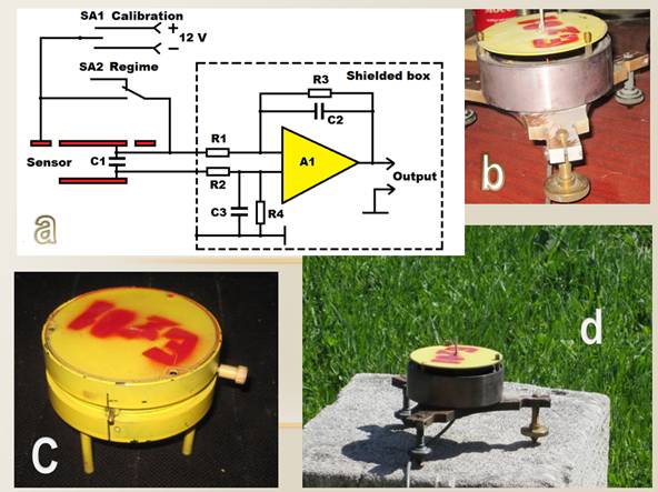
Fig.1. A simplified scheme of the field voltage converter EV is made
with the use of MDM-amplifier (a) and general view of
various ES designs (b), (c) and (d).
The operation of the circuit is as follows. The
flow electrostatic induction measured EF induces an electric charge on the
sensors measuring plates, which is made in the form of a flat capacitor.
Further, with the help of the electronics box (EB), is the transformation of the electric field – current –
voltage – digital code, whereby on the recorder (e.g. on the display of a
personal computer - PC) is indicated by process changes (variations) of EF in
time, and the digital data recorded on the hard disk (or flash drive) in a PC.
At the input of the amplifier A1 (to improve its
stability covered both internal and external negative feedback) is a precision
modulator which converts the input DC voltage to the amplitude of the AC. Next,
the AC signal is amplified and is demodulated by a synchronous demodulator,
which allows to maintain the linearity of the conversion and small zero drift.
MDM-amplifier circuit performs the function similar to the exposure plates in
the sensors-"turntables" [4, 6, 7, 11], which periodically with the
frequency of rotation of the ground (exposed) potential EF, achiever the
working plate charging. That is, with the period of the operating frequency,
which is MDM transformation, MDM-amplifier controls the change of the potential
difference on the working of measuring plates. The output of such a converting
is a slowly varying voltage proportional to the change in EF between the measuring
plates. This scheme of input part of the EV has a low level of noise, high
sensitivity and very low “zero drift”. The performance of the amplifier circuit
A1 is limited in our case, the value of the carrier frequency (110-130 Hz) at
which the signal conversion.
The main part of the scheme was implemented on
the basis of the operational amplifier (OA)
type 140 UD13 and placed inside the grounded housing of ES under measuring
plates. The ES connection with the recording equipment located in the technical
building, was carried out by means of connecting shielded cable of 25 m length.
Power schemes EV was carried out using the AC adaptor (SA) with 12 V DC from AC.
In early 2012, created a new design ES shown in Fig. 2a, Fig.2c and Fig.2e, which differed from the
previously described sensor of EF the fact that there was no built-in
electronic unit, as well as were designed protection from bad weather
conditions for use of MP in conducting continuous research. ES is designed to
work in open atmosphere. Operating conditions: temperature from -50° to 50°C,
humidity ≤100%, pressure 750 ± 30 mm Hg.St. The
dynamic range of the measured values of variation of the EF intensity from 0 to
± 1500 V/m (regulated and had the ability to scale by means of specially
written programs for the PC).
In the same year, has been designed and developed
EV new design described in [15], and a general view of the ES is shown in Fig.2b and Fig.2d. Case of ES is made in the form of a flat cylinder with a
diameter of 120 mm and a height of 40 mm (see diagram in Fig.1a.), within which are mounted: MDM-amplifier, integrator,
bandpass filter and DC-DC converter and control circuit for the calibration of
the device. The measuring plates of this sensor EV are flat (sectional) metal
plate thickness of 1 mm and a diameter of 240 mm, mounted on the insulator
polycarbonate at a distance of 10 mm from each other. On the sensor housing are
EV controls, which are the inclusion and calibration of the sensor.
MDM-amplifier was made on the basis of OA type
ICL7650, which had a high input impedance (10¹² Ohm), low temperature
coefficient (0,01 µv/°C) and very low drift over time (100 nV/month).
This OA was already a higher frequency compared to the previously used, the
operating frequency of MDM-conversion was in the range from 120 to 375 Hz. All
the ES and EB schemes were powered a constant voltage of ± 5 V from the power
source, which used rechargeable battery (RB)
voltage 9...24 V (in the field) or standard SA when powered EV from AC voltage
of 220 V and frequency 50 Hz, the consumption of the device was not more than
1,2 VA. The cable, which will connect ES and EB, were screened and had a length
(at different points in experimental studies) from 10 to 25 m. With this cable
were feeding the supply voltage for all ES circuits, as well as the
transmission of analog data in EB. Further, by using located in EB of 24-bit
ADC (based on the AD7734 chip), the analog data is converted into digital form
and then supplied to the registrar, as using a PC.
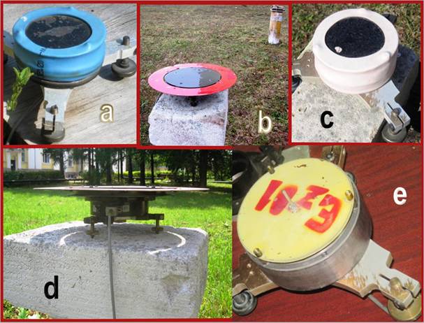
Fig.2. General view of various ES designs installed in
MP to IP.
III. THE THREE-CHANNEL ELECTROMETRIC
VARIOMETER
All created by the EP sensors
have different sensitivity and to compare them with each other in scale and in
time, was designed multichannel data acquisition system, functional sheme of
which is shown in Fig.3. This system
includes three measuring channel and was created based on EB, which was used in
the devices described in [13, 14], but without the positioning systems and
systems connected with the wireless transmission distance.
EB included three-channel
amplifier (US), a control circuit (CC), control microprocessor (CMP), ADC, and power supply unit (PSU). To control the temperature of the
external environment used precision integrated temperature sensor (DT) made on the basis of LM35 chip connected
to one of the ADC channels. When powered EV from AC voltage of 220 V and
frequency 50 Hz device consumption was not more than 1,5 VA.
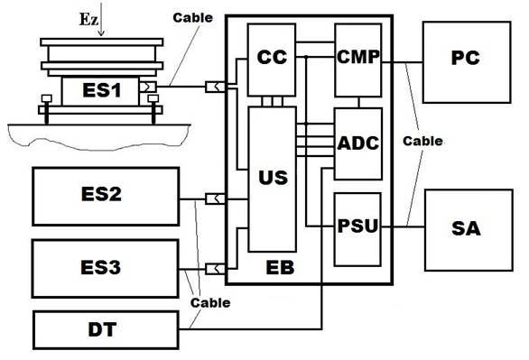
Fig.3. A functional sheme of a three-channel
EV.
Structurally, EB was performed
in a metal box dimensions 225х145х80 mm, on the side
panels which are all the controls for EV and connectors to connect the three ES,
SA (or RB) and PC. The device is
designed for long continuous operation in any weather, both in the field and in
the Observatory conditions with the installation of the ES on a pedestal, on a
special stand outside the room (on MP) or on the measuring post (IP). Connecting ES with EB was carried
out using a shielded cable type UL2464 4C and 9C (see Fig.3) different lengths depending on the distance from MP to IP.
IV. METHODICAL WORK
For testing sensors EV was organized measuring polygon (see Fig.4), which includes technical
building (pavilion) and measuring poles (IP). In the technical building recording
equipment (PA) system three-channel
EV, which includes EB, SA and PC. All was arranged five MP, four IP (C1...C4), which were
located on both sides of the technical building, and one of MP (C5) is
mast-mounted above the roof of this building at a distance of 10 m from the
surface of the Earth. EV sensors were located on the IP from different sides of
the pavilion in the direction East-West. Extreme of these IP separated from
each other horizontally at a maximum distance of 30 m.
The
IP was located at a different fixed distance from each other and from the
Earth's surface. On these measuring poles alternately or simultaneously varying
the investigated sensors in various combinations. General view of the technical
building, measuring polygon (top view and side view) and IP (C1...C5) fitted ES
shown in Fig.4.
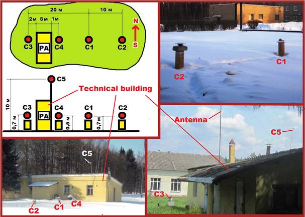
Fig.4. The scheme of technical
building location and IP with ES at the measuring polygon.
About 50 meters from the measuring polygon was located in the building
of ionospheric stations with a high radiating antenna, which can also be seen
in Fig.4. Periodic radiation of this
ionospheric station has had a strong influence on the measurement of EF in
various MP, when carrying out methodological work on the measurement range.
Radiation station in addition to the generated interference, which is shown in
the records of EF in [15], were (and still used) as a "calibration
part" of the whole EV measuring system and served as a positive when
comparing the ES sensitivity if they are both installed on the same IP. It
should be noted that all of the ES every 15 minutes felt a strong
electromagnetic effect (with different frequency and amplitude of the radiated
high frequency signal) and back to normal mode register EF without displacement
of their "zero level".
Examples of the registration of different amplitude and different
frequency of impacts of the emission spectrum of the ionospheric station on the
ES measurement installed in three MP (C1, C4 and C5) on the measuring polygon
shown in Fig.5. Recording EF made by
PA in real time with a speed of 16 measurements p/s.
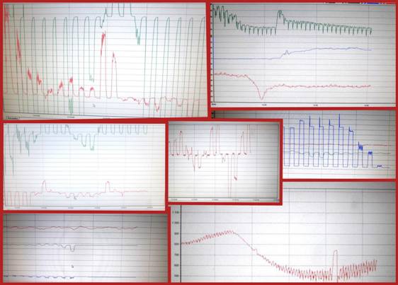
Fig.5.
Examples of the ionospheric station influence on the EV measurement results
located
near to the measuring polygon (record
in MP on the IP C1, C4 and C5).
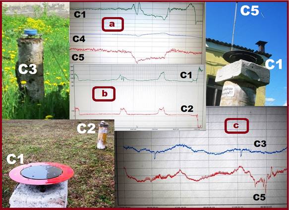
Fig.6. Fragments of the daily
and three-day EF recording in MP at the
IP (C1- C5).
In Fig.6 (a, b , c) shows fragments of different EF combinations records and different designs of ES in a different time period. Here are
fragments of the one - and three-day records of EF on different IP as well as
recording three-channel EV (at different scales). As can be seen from the
fragments of the entries of EF in various MP behave differently and have
(according to MP position from the Earth's surface) is different (not exactly
the same).
V. THE MORPHOLOGY OF SOME NATURAL PHENOMENA
During and in carrying out methodological and research studies on work
created of EF sensors, which lasted for nearly the past 6 years, there have
been many experiments and obtained interesting data in digital form on the
behavior of the ES and the change of EF in various MP by simultaneous EF registration
of multiple EV working sensors. Illustrate some interesting points at check EF
in the process of conducting continuous works are shown in below figures. Here
shows examples of the change EF registration of EV sensors under different
weather conditions.
In Fig.7a shows fragments of
the daily and three-day records EF with the change of solar activity in the
summer time for the IP (C4 and C5,- see Fig.4)
located in MP vertically one above the other and at a distance from the surface
of the Earth, respectively, 0,5 and 10 m.
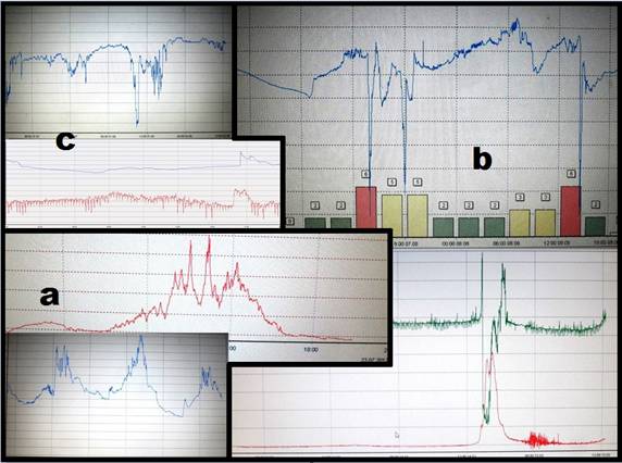
Fig.7. Fragments
of the daily and three-day EF records, when the daily change of solar activity (a), in moments the passage of lightning
discharges (b) and in the form of
rain or heavy rain (c).
In Fig.7b is depicted on the
PC screen fragments one-day and three-day registration of the EF change in
moments the passage of lightning discharges. Illustration applies to all three
measuring EV channels, registration of which was conducted in a continuous mode.
Records are made ES located on the IP of C1, C4 and C5 and reflect the
registration process in the vertical plane (at different levels MP embed), in
the gradient mode variations in height.
In Fig.7c presents fragments
of single-channel and dual-channel recording on the PC display EF changes
during a sudden rainfall in the form of rain or heavy rain. Here are records of
this phenomenon in various EV recording resolution. Digital registration in
this case was conducted with the greatest possible speed (16 measurements p/s)
and averages data in a time interval of 1 s. The visualization of the
measurement process on the PC display was made with averaging of digital data
at a minute time interval.
VI. CONCLUSION
In the
result of carried out works and experiments created and passed a long test of
prototypes of the sensors for measuring the electronic signature of different
types and designs that showed its full functionality in various applications.
Created sensors and the EV system enables continuous long term measurements of
EP under different weather conditions. Receiving data in digital form allows to
accumulate these data to create a database and use them for conducting various
kinds of analytical studies.
Analysis of
the data showed that EF at the location of the sensors in the atmospheric
boundary layer (where is a large part of human activities) is inhomogeneous and
its behavior is different in different measuring points located at different
heights from the ground level. Changes EP here come under the influence of
various anthropogenic and natural processes. Therefore, the establishment of
the measuring network EF, as is done (for "pure science") by ROSGIDROMET
institutions and others in specially designated and equipped "clean
places", gives a complete picture of the process of change EF in space and
some of its laws.
For
comprehensive research in this area is necessary to create sensors and systems
(multi-sensor and multi-channel) with digital signature, is able to give
continuous information in any place of their installation. In particular it
needs to be done and for projects related to electromagnetic compatibility of
equipment and the increasing risk associated with increasing number of emitting
household equipment, its electromagnetic effect on the human environment.
VII. LITERATURE
1. Imyanitov I. M. Devices and methods for the
study of atmospheric electricity. M: Gostekhizdat,
1957. - 483 p.
2. Imyanitov I. M., Chumarina
E. V. Electricity of the free atmosphere. Leningrad: Gidrometeoizdat,
1965. – 240 p.
3. Afinogenov L. P., Grushin
S. I., Romanov V. E. Apparatus for research in the atmospheric surface layer. -
L.: Gidrometeoizdat, 1977. - 319 p.
4. Shvarts Ya. M.
Rotary converter of the atmospheric electric field to AC current. Copyright
certificate №558241 G01W1/16. Published 15.05.1977. Bulletin of inventions No.
18.
5. Zykov M. V., Yunda
T. N. The analysis of the input circuit of the electrometer with reverse
connection // Metrology, 1981, №5. P. 58-62.
6. Sensor of electric field intensity "FIELD-2". Technical
description and manual. Leningrad: USSR State Committee for Hydrometeorology,
1989. – 35 p.
7. A device for measuring electric field strength. Technical description
and user manual. Rostov-na-Donu:
Radiation physics environmental center, research Institute of physics, Rostov
state University, 1990. – 5 p.
8. RD 52.04.168-2001. The observations of atmospheric electricity.
Methodical instructions. 2002. – 31 p.
9. Grunskaya, L. V., Electromagnetism surface
layer and its relationship with geophysical and astrophysical processes.
Vladimir: Posada, 2003. -103 p.
10. Electric field meter Vaisala EFM550. Prospect
of VAISALA. – 4 p. (www.vaisala.com)
11. Anisimov S. V. Device for measuring the
electrical conductivity of the atmosphere. RF patent № 2397515 G01W1/16
G01R29/12. Posted 20.08.2010.
12. Kopeikin V. V. Use of surface electric
field for detecting underground inhomogeneities //
Geomagnetism and Aeronomy. Moscow: Nauka, 2011. Volume 51, No. 5. P. 690-694.
13. Kiriakov V. Kh.,
Lyubimov V. V. Digital magnetic automatic variation station // Dynamika naukowych badan – 2012 / Materialy VIII Miedzynarodowej naukowi-praktycznej
konferencji 07 – 15 lipca
2012/ Fizyka. Vol.22, Przemysl.
2012. S. 31-35.
14. Lyubimov V., Kiriakov V. Digital autonomous
automatic station/Exhibition centre of the Russian Academy of Sciences. M. 2012
(http://www.expo.ras.ru/base/prod_data.asp?prod_id=5300).
15. Lyubimov V. V. Electrometric variometer //
Sensors and Systems / Design and manufacture of sensors, devices and systems. New
appliances. M: "OOO SenSiDat", 2014. No.2.
P. 47-48.