Key
words:
spot
welds, ultrasonic quality control.
Investigations of spot welds quality
based on ultrasonic techniques
A. Ambroziaka*, M.
Korzeniowskia, P. Kustrońa
a
ul. Łukasiewicza 3/5 50-371
*E-mail
address: andrzej.ambroziak@pwr.wroc.pl
This article contains some information about the main methods of
ultrasonic quality control of spot welds. Resistant welding process is very
sensitive for lots of factors like: electric power excursion, electrodes and
material surface’s condition, electrical by-pass, etc. It usually causes worse
quality of the connection. To prevent this factor’s influence, many methods are
being investigated. Recently, many of the promising methods are based on
ultrasonic waves. That’s why we would like to present advantages and
disadvantages of two systems.
First, OFF-LINE method can give us information about typical
unconformities of spot welds but only after the process. This method is very
popular nowadays especially in thin-walled materials. It lets to check the
quality of even a hundred percents of spot welds without destroying them.
Second ON-LINE method is based on measuring selected parameters of
ultrasonic wave, which flow across the spot-joins during welding process. It
cause that we can check quality of spot weld during its arising. Diagrams of
ultrasonic transmission shows that ultrasonic method can give many, important
information about welding process, like: size of welding nuggets, it’s arising
and crystallization moment but first of all, current switching-off moment. All
abilities of this method can be used to find weld quality, controlling welding
process and prevent many dangerous factors in the time of weld arising.
1. Introduction
The resistance spot welding is the most popular method of joining steel
sheets.
The connection arises by passage the current and action of welding force.
Heating of joining parts is an effect of heat generation on electrical
resistance of welding circuit.
The resistance spot welding is the process of welding by which the
joining parts are pressured by welding electrodes which conduct welding current
into the spot weld [1]. Connecting 2 or 3 parts of sheets is possible by the
resistance spot welding. During this process one or more welding joints can be
obtained. It depends of applied welding machines. The resistance welding
process is quick, efficient. This is the reasons why the spot welding is the
most popular kind of joining in automotive industry (manufacturing bodies,
chairs and many others). The spot welds are mainly performed by robots. Because
of the fact that welding machines are unreliable, spot welds can have some
defects.
Unconformities which can appear in spot welds causes the spot welds can
have less strength and can lead into total destruction of manufacturing parts.
The typical unconformities of spot welds are [2][3]:
·
cold weld,
·
small-diameter of spot weld,
·
bad shape of the nugget,
·
cracks inside/around the nugget,
·
deep indentation of welding
electrodes in sheets.
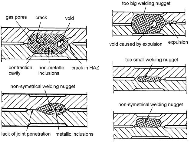
Fig.1. Typical flaws in spot welding joints [3].
In automotive industry the elements of cars bodies are joined by
resistance welding. The best quality of welding joints is very important. On-line systems aren’t developed enough, so
at the present it is impossible to control all spot welds.
The non-destructive method which can be applied to test the quality of
spot welds is ultrasonic off-line method. Ultrasonic systems are in common use
from ages, but testing of thin plates generates a lot of problems. The upper
range frequency of typical ultrasonic transducers used to flaws detection is
10MHz. It limits the thickness of the tested plates to 3mm so to test
thin-plate spot welds applying the higher frequency is required. The range of
plate-thickness in automotive industry is from 0.75 to
2. OFF-LINE ultrasonic tests
There are two principal ultrasonic methods used to detect unconformities
inside spot weld. The first one is the pulse-echo method the second one is the
flow method. To test quality of spot welds in automotive industry the
pulse-echo method was used.
This method implicates applying one ultrasonic head worked alternately:
as a transmitter and as receiver.
It
consists of ultrasonic transducer which generates longitudinal vibrations.
Ultrasonic beam flows across the delaying path which is ended by an elastic
membrane.
The homogeneity of spot weld determines the back-wall reflection. The
multiplied reflections are observed at the flaw detector. In case of internal
unconformities (e.g. gas pores) the signal observed at flaw detector is an
effect of reflection from the unconformities.
It’s possible to determine distance from unconformities to ultrasonic
head.
To
determine the quality of spot welds mostly following factors have to be taken into
account:
-
numbers of back-wall reflections,
-
attenuation of ultrasonic wave (in dB),
-
numbers of reflections from flaws,
-
envelope of echoes.
Dimensions of the defects, measured by ultrasonic tests, can diverge
from their real size. It comes from different reflecting ability of variety
reflectors. A shape, diameter and structure of the defects and ultrasonic waves’
parameters are main factors which determine their reflecting ability. Moreover,
a diameter of the ultrasonic transducer and a distance between ultrasonic head
and the defect are very important.
The best reflecting abilities have these planar discontinuities which
are oriented perpendicularly to the wave’s flaw direction.
The experimental spot-welds joints were checked by using the echo
method.
The results of the ultrasonic tests were verified by destructive tests
(metallography).
|
Metallographic picture |
Ultrasonic diagram |
|
Good spot-weld |
|
|
Incomplete
fused joint |
|
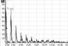
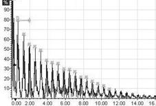
Fig.2.
Results of spot-weld inspection [15]
Figure 2 shows two different cases: good and incomplete fused joint. In
the first case, the result of ultrasonic test reveals good quality of the
spot-weld. First diagram shows short sequence and high dumped consecutive
pulses. It testifies about good quality of spot-join. Metallographic test
confirms that fact.
The
second case describes incomplete fused joint. Second diagram shows long and low
dumped sequence of pulses. It proves the lack of the nugget.
3. ON-LINE ULTRASONIC QUALTIY CONTROL
OF SPOT WELDS
Popularity of spot welding process and application of spot welds in
responsible constructions have caused the need of controlling the welding
quality while the process runs. The aim is to minimize the quantity of faulty spot
welds and control the process.
There
are plenty of methods, which allow for quality control of produced joints.
They are mainly base on measuring:
·
current, voltage and dynamic
resistance [10], [11],
·
transmission and velocity of
ultrasonic waves[12][13],
·
thermal expansion [16],
·
infrared radiation [16],
·
acoustic emission [16].
These
methods have a range of advantages and disadvantages. In case of controlling electrodes movement during the
welding, acoustic emission, infrared radiation or ultrasonic method it is
necessary to apply very complicated measuring apparatus.
Method
of measuring dynamic resistance becomes more and more popular [10], [11]
However each of above mentioned methods allows to receive only specific
information about the welding process.
Systems
described below, bases on measuring the amplitude of ultrasonic waves.
There
is a few technological solutions elaborated by different concerns, but its
functioning principles are similar [18] [19].
On
basis of researches conducted by Welding Establishment of Wrocław
University of Technology it has been claimed that, there’s strict correlation
between amplitude of ultrasonic wave measured while welding process and quality
of produced joints.
In application that was used for measuring, ultrasonic heads were placed in
proper construction.
a) b)
b)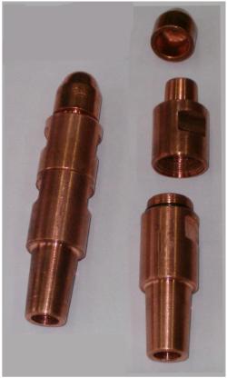
Rys. 3. Construction of electrodes
a) scheme , b) picture.
On base of ultrasonic wave transmission curve – measured during the
welding process, we can classify given spot weld to estimated quality category.
The ultrasonic wave transmission curve gives us also a lot of information about
the process that occurs in arising weld joint. Those are eg. forming of liquid
nugget, its growing and becoming a solid phase.
Researches that have been made so far now predicate mainly on measuring
the only one ultrasonic wave parameter – it is transmission of the wave flowing
through arising spot weld. That’s why it is justifiable to pay attention to
other parameters such as velocity and wave passing time from transmitting head
to receiving head, during the welding process.
The
velocity of ultrasonic wave is typical property of medium in which it spreads.
Its value is different for solids, liquids or gases, even for different kinds
of metals. Moreover the relevant factors that determine the velocity of sound
spreading in given mediums are their density and Young’s module.
During the resistance spot welding process
the changes of above mentioned parameters follow, as an effect of substantial
changes of material temperature. Especially Young E module, besides frequently occurs
a change of condensation state (e.g. becoming of liquid spot weld nugget).
Due to this, in compound of arising spot weld, substantial ultrasonic
wave velocity changes will follow, and the same crucial changes of passing time
between transmitting head and receiving head too.
Fig.4. Diagrams
of ultrasonic transmission, received for
(1mm thickness) mild steel and various welding current.
As well as from perspective of produced spot weld quality and from controlling
of this process, the most important area of transmission diagram is current
switch-off moment. According to observed
and registered diagrams, there have been claimed that it illustrates the spot weld
quality in most precisely way.
Figure
4 shows three registered tracks of wave crossing through spot weld while the
jointing process. We may notice that with the welding current growth, also rises
the value of ultrasonic wave transmission.
Fig.5. Time of
flight diagrams, received for
(1mm thickness) mild steel and various welding current.
Figure 5 illustrate the
results of measuring Time of Flight - TOF[ns] of ultrasonic wave through subsequent mediums, these are: liquid
coolant, material of electrode and joined materials. As a result of changes
these mediums’ temperature the wave spreading group velocity also changes. Of
course the time in which the wave reaches receiving head. Due to this, the
direct time measuring has been made actually, and is quoted in nanoseconds
- on figure 5.
Registered diagrams (fig.4 and
5) reflect the spot welds produced with different values of welding current. In
this way have been obtained joints in different quality categories (beginning
with sticking – with welding current Iz = 6,1kA, through to small spot
weld nugget – class C – with welding current Iz = 7,8kA, on perfect one spot weld in A class
ending – welding current Iz = 8,6kA).
4. CONCLUSION
On the ground of presented results, it was found that in spot welds of thin
walled elements:
·
Ultrasonic tests can be apply to
prove their quality
·
Examination requires using special
ultrasonic heads equipped in liquid intermediate medium to improve a contact of
ultrasonic head with spot weld surface,
·
Application of ultrasonic waves
during the spot welding process provides a lot of important information about
arising spot weld and run of the welding process.
·
Ultrasonic quality control is very
promising method but its applying should be verified by metallography.
5. REFERENCES
[1] A. Klimpel: Spawanie zgrzewanie i cięcie
metali, WNT Warszawa1999.
[2] H. Papkala:
Zgrzewanie oporowe metali, WiHK „KaBe” s.c. Krosno, 2003.
[3] A. Klimpel: Kontrola i zapewnienie jakości
w spawalnictwie. WPŚ Gliwice 1998
[4] W. Roye: Die Ultrachall Priifung
von Komponenten und Fugeverbindungen
im Automobilbaum, DGZfP
Berichtband 79-CD, 1999.
[5] R. Rosenberg:
Ultraschallprufung und Dieckenmessung rund ums Automobilbau, Panametrics
Hofheim-Wallau 1999.
[6] Krautkramer Company
Journal „Echo
[7]
A. Lewinska-Romicka: Badania nieniszczące, podstawy defektoskopii, WNT,
Warszawa, 2001.
[8] Ultrachallprufung von
Widerstandspunktschweifiyerbindungen im Karosseriebau der Volkswagen Sachsen
GmbH, DGZfP Berichtband 79-CD, 1999.
[9] C. Kohler: Die Einfuhrung
der Priifung von Widerstandsgeschweifiten Punkten mittels Ultraschall in der
Automobilindustrie – Uberblick der Entwicklungen und Activaten der lezten
Jahre, DGZfP Berichtband 79-CD, 1999.
[10] J. Kozaczyński, Z.
Mikno, P. Stodolny: System do kontroli jakości połączeń
zgrzewanych w oparciu o sieci neuronowe, Seminarium Instytutu Spawalnictwa,
Gliwice, 2004.
[11] A. Straube, A. Torzewski, B. Winien: PQSweld –
System kontroli dla zgrzewania punktowego i
garbowego na bazie fuzzy logic. Podstawy, możliwości i
zastosowania praktyczne, Seminarium
Instytutu Spawalnictwa, Gliwice, 2004.
[12] A. Ambroziak, Z.
Koralewicz, M. Korzeniowski, P. Kustroń: Kontrola jakości powstających zgrzein metodą ultradźwiękową, Prace Naukowe
Instytutu Technologii Maszyn i Automatyzacji PWr., Zeszyt nr 73.
[13] A. Ambroziak, L. Krynicki, Z. Koralewicz: Określenie
przydatności badań ultradźwiękowych do oceny jakości
połączeń zgrzewanych punktowo, Przegląd Spawalnictwa Nr
7-8/2000.
[14] A. Ambroziak, Z.
Koralewicz, M. Korzeniowski, P. Kustroń: Badania ultradźwiękowe
zgrzein punktowych, Spajanie metali i tworzyw w praktyce,
Nr 1/2005.
[15] A. Ambroziak, A. Kisiel, M. Korzeniowski:
Zastosowanie badań ultradźwiękowych do oceny zgrzein w
cienkościennych elementach stalowych, Przegląd Spawalnictwa 5-7/2004.
[16] S. Piech: Kontrola adaptacyjna w procesie zgrzewania oporowego
punktowego, Przegląd Spawalnictwa, nr 5/1983.
[17] E. Talarczyk: Podstawy techniki ultradźwięków, Wydawnictwo
Politechniki Wrocławskiej, 1990.
[18] VOGT
Werkstoffprüfsysteme: Inline
ultrasonic testing system for process control during resistance spot welding, www.vogt-ndt.de.
[19] Bosh Rexroth: Automatic
ultrasonic tests – non destructive during the welding process, Materiały
konferencyjne,