Operating
damages of air turbine scoops of turbo - engines
Ph.D. D.Sc. Janusz Szymczak, Ph.D. D.Sc. Andrzej Szczepankowski
Air Force Institute of
Technology (ITWL)
6 Ksiecia Boleslawa
St., P.O. Box 96, 01-494 Warsaw 46, Poland
tel.:+48 22 6852210,
e-mail: assz@op.pl
Abstract
The paper presents various types of
turbine scoops damages that are being found in the operating process of air turbine
engines (TSO). When dividing them, having in mind a genesis of their origin, a
special attention has been paid to corrosion and high-temperature erosion,
often being a reason for destruction of the entire unit.
The damages hereto described have
been illustrated with examples collected during endoscope surveys of TSO internal
spaces or their post-failure disassembly. The summary points out to the ways
and directions of works aiming at early detection of TSO turbines units
damages, and thus at improvement of their operating safety.
Key words: turbo-jet engine, turbine, damages,
corrosion, erosion, operation, prevention.
Introduction
Many years of experiences and
observations as well as a result of air accidents investigations, performed by
the authors of this paper, have indicated that in the air TSO operating process
there are various types of scoops blades damages of turbine units, thus
limiting technical installation life. Their causes can generally be divided
into: construction design-based, productive, and operating. And the latter ones
into: mechanical, chemical, and thermal. They may become centres of wearing
cracks of one or more of scoop blades and a cause for their partial or total
destruction, which in turn often leads to damages of those neighbouring with
them in the blade-ring or in the subsequent levels of the turbine unit. In a
consequence it results in engine failure, premature dismounting thereof from
airframe and ordering it to be repaired.
Also wearing cracks, mechanical and
thermal deformations, overheatings and burnouts or chemical corrosion as well
as mechanical and gas erosion are the main cause for premature withdrawal of
TSO from use, and not detected in proper time can become a danger for their
users.
This paper presents various types of
examples, being found in the operating process, and blades damages of TSO air
turbines units.
Damages effecting from a design of
turbine rotor ring
Wanting to obtain the
largest possible efficiency of TSO turbine level, various types of solution
designs are applied which, on the one hand, by minimising tip clearance reduce
loses of working medium flowing through it, and on the other hand, they stiffen
the rotor ring.
1

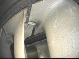
Fig.
1a. View in direction of a surface of cooperation between two, neighbouring in
a ring and coming subsequently one after the other, locks of plates of node
shroud of scoops blades of 3rd level rotor of „89” type of engine turbine [1,
6], 1 - a cooperation surface of
distance plates of node shroud locks
One of such
solutions has been illustrated on Fig. 1a where by using node shroud plates
(anti-vibration plates) of blades, having a complicated lock shape with
distancing plates melted-in during the TSO production or repair process in
place of cooperation of the turbine level scoops neighbouring with each other
in a ring, and by introducing initial torsional stresses (assembly tension)
when building them into a carrying disk, its ring tightening has been achieved.
However, when using this type of
engine, such a solution design results in a need to realise its technological
regeneration process that is not less complicated.


![]()


![]()


![]()

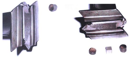
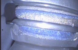
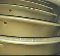
Fig. 1b. View of
external surface of node shroud plates of operating scoops of 3rd level of a turbine of „89” type of engine [1] (1 - raw material of distance plate type 89.0420148.2, 2 - raw material of distance plate type
EG89.041421)
During TSO operation, as a result of natural
wearing of distance plates of the node shroud in places of their cooperation
(see - Fig. 1a, e) or mechanical damages caused by their chipping off, there is
an increase of total, circumferential assembly clearance and of such values
that may generate resonant-alike vibrations or even resonant vibrations in the
ring.


![]()
![]()
![]()
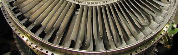
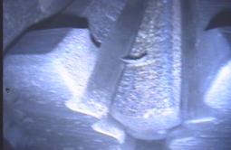
Fig. 1e. View of 3rd
level of turbine rotor of „89” type of engine. c ÷ d - the remaining in
the carrying disk fragment of multi-trapezoidal lock of a scoop broken out from
the ring [1]
This in turn may result both in the carrying
disk lock itself and under the plate of blade shroud in a growth of stresses to
critical values. Therefore, it is not difficult to figure it out that exceeding
them may cause initiation of wearing cracks that as the end result will lead to
breaking out one of the scoops from the lock of the carrying disk and to a
damage of a turbine unit (see - Fig. 1c ÷ e) [1].
Production
and repair causes of turbines scoops damages
Those types of damages rarely occur in air TSO. Nevertheless, it
happened over the past few years that two cases occurred that entire blades of
scoops broke out from rings of rotors of SO-3 type of engines - see Fig. 2a. As
a result of the-then conducted investigations it was found that the cause of
that was an error made in their production process, as not only that blades of
scoops were covered with chromo-alliterated layer but also their
multi-trapezoidal locks. This led to increasing local surface stresses in locks
spaces and to generation of microcracks (see - Fig. 2b), which in consequence,
as a result of TSO operation, caused breaking out of one of scoops blades in a carrying disk lock of the
rotor unit.
|
|
|
|
Fig. 2. Fragment of
turbine rotor of SO-3 type of engine with a scoop broken out from the ring
(a). Crack of the scoop on the radius of a passage of the blade neck into a
multi-trapezoidal lock (b) [6] |
|
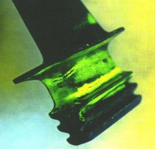
However, such cases occur as that
illustrated on Fig. 3 when first a burnout of insulation-protective layer had been
found on the surface of the edge of the scoop blade of the high-pressure
turbine rotor TSO (see - Fig. 3a), and then after it was repaired the same
scoop looked as the one illustrated on Fig. 3b, which already may raise some
doubts of the user as to quality of the performed improvement of the exemplary
element or its regeneration technology itself.
![]()
![]()
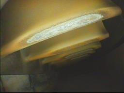
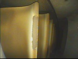
Fig. 3. Fragment of
high-pressure turbine rotor of „88” type of engine [6]. a - burnout of
insulation-protective layer from the part of the blade attack edge surface, b -
view of the fragment of repaired scoop blade
And this type of doubts could have
been raised by earlier supervision of the use of AI-25 type of engines and the
example of which has been illustrated on Fig. 4.
On the surface of the
scoop preceding the damaged one, there is a clearly visible „surface
discontinuity”, which only means that during the renovation the old
insulation-protective layer was not cleared from it but only the damaged part
was filled in without caring for a correct operation of that of the working
injectors whose operating quality influenced its earlier condition.
![]()
![]()
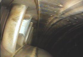
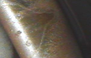
Fig. 4. Fragment of a palisade of steering gear of
high-pressure turbine of AI-25 type of engine [2]. a - burnout of
insulation-protective layer from attack edge surface and the blade rim, b -
view of the fragment of repaired scoop blade with high-temperature corrosion
pits
However, it did not protect it from
damage as after some time high-temperature corrosion craters were found on its
surface - see - Fig. 4b.
Mechanical
damages of turbine scoops
Long-term visual
research using endoscope method and related to them analysis of technical
status of TSO subcomponents allows for making some generalisations referring to
initiation of their damages. Therefore, events effecting from sucking in
foreign matters should be considered to be the basic cause of mechanical
damages of compressor and turbine unit. It happens on the random basis or it
results from taking off or landing on casual landing grounds. Nevertheless, one
also cannot ignore here a lack of proper carefulness of technical personnel for
keeping ground surface clear, or engine intake. However, there are such cases
the cause of which may also be incorrectly made protective coating and its
later erosion damages.
![]()

![]()
![]()


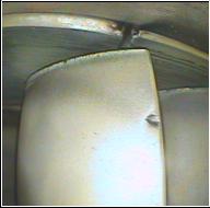

Fig. 5. Fragment of turbine rotor of high (a ¸ b)
and low (c) pressure type of engine „88” [3, 6]. a - a dent on a surface of
blade attack edge, b - a dent on a surface of the rim (close to the edge of the
blade flow) and c - numerous, small-area dents on a surface of the blade rim
And the fact that those types of damages are rather typical for TSO
compressors units does not necessarily mean that they are not found on turbines
scoops, as dents occur also on their surfaces (see - Fig. 5), or scratches of
insulation-protective layer thus becoming a source of local concentration of
tresses or a corrosion centre, which in this case as on Fig. 6 may lead after
some time to perforations and cracking of the blade.
![]()
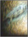
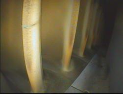
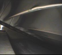
Fig. 6. Scratch of
insulation-protective layer with
Fig. 7. A dent of the rim surface with a simultaneous
with corrosion centre on the surface
of attack buckling of
attack edge of scoop of turbine rotor
edge of the scoop blade of high
pressure of
SO-3 type of engine [6]
turbine rotor of „88” type of engine [6]
This type of damages
does not necessarily have to effect from sucking in of foreign matters by TSO,
as the same may be caused by tearing off products of incomplete combustion
(carbon deposits) in the combustion chamber and their crashes with turbine unit
elements, as it happened in case illustrated on Fig. 7.
Thermal
damages of turbines scoops
The source of damages, illustrated on Fig. 8 b ÷ c, was an
incorrect organisation of the combustion process as during operation of the
engine there was an occurrence of a local, short-lasting lengthening of the blend
combustion zone and its relocation in direction of further sections of
combustion chamber flame tube, thus giving a cause to possible further burning
of fuel vapours in a space of palisade of steering gears during ignition of
TSO. Changes in the surface status that have been found in those places prove
how significantly the process was going through periodical interference.
However, in case of this type of TSO, it is easier thanks to a construction
design of combustion chamber unit itself because nozzles axles of operating
injectors face in it straight towards bottom sediment rings of steering gears.
|
|
|
|
|
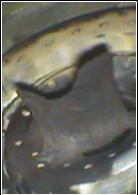
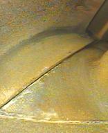
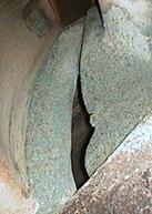
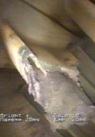
Fig. 8. Fragment of fuel
injector and palisade of steering gears of high-pressure turbine of air
turbo-engine type AI-25 [6]. Subsequent phases
b ÷ c of corrosion-erosion „washout” of material of bottom feet of locks
of two steering gears blades neighbouring with each other in a palisade
It is essential
as at simultaneous, incorrect match of nozzles diameters, or when surfaces of
operating injectors had carbon deposits (Fig. 8a) and thus effecting in a
change of geometry of fuel spray cone, first there was an occurrence of
overheating and burning out of insulation-protective layer in those observed
places, and later of a gradual and „up to disappearance” of a part of the blade
(Fig. 8d), „washout” of its material, which was not even prevented by the fact
that they are cooled with air taken from compressor space.
The fact that the above-presented process of TSO destruction was going
in a long period of time, and which probably had already started at the moment
of its delivery to use, is proved by traces of corrosion and gas erosion as one
of its forms was the aforementioned „washout” of material from parts of
surfaces neighbouring with each other in a palisade of steering gear blades
(Fig. 8c). This was also accelerated by allowable presence of residual amounts
of W, Mo or Co, and first of all sulphur compounds in fuel, as Jet A-1 (F-35)
type of aviation fuel, being produced in compliance with military defence standards,
may contain a maximum up to 0.3% of S in its volume unit, and this in turn
causes that SO2 contents in combustion fumes may even reach ca.
0.014% [4]. This leads to a conclusion that the higher contents of this element
in fuel the higher contents of SO2 and SO3 in combustion
fumes, which in turn results in a higher threat of turbines damages in view of
inter alia incorrect organisation of its combustion process.
Chemical damages of
turbines scoops
Chemical damages of turbines scoops
are first of all corrosion leading to surface pits and in its consequence
cracks of blades.
![]()
![]()
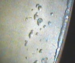
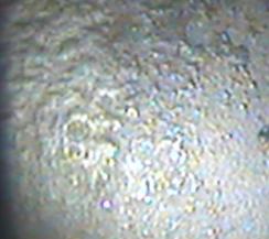
Fig. 9. View of
fragment of the scoop blade groove of turbine rotor of SO-3 type of engine used
in environment of
higher contents of sodium chloride [6]. Two subsequently commencing
phases one after the other a) ÷ b) development
of sulfide-oxide corrosion
A failure
in the production or repair process to observe respective parameters for
putting protective layers also has a large impact on generation and development
of this type of damages as that in case of the illustration presented on Fig. 9
was a likely cause of occurrence of the damages found. This is proved not only
by their character but also by location of their occurrence because they are
found on those surfaces which are the most exposed to influence of temperature
and contents of the flowing combustion fumes, that is, on the attack edges and
the groove. It should however be added here that the working environment itself
of TSO being tested also had some influence on acceleration of this process,
which in this case indicated a large content of sodium chloride.
The above picture was used to
illustrate recognised in references [4] two first phases of development of this
type of corrosion, however, on Fig. 9a there is a visible fragment of surface
the protective layer of which has been damaged still on a small area, and being
characterised with a small growth of its roughness and just cracking oxides
bubbles. However on Fig. 9b, it is noticed that the extension of the work time
of the scoop in the aforementioned conditions led to further development of
oxidation of its protective layer and it growing roughness, and due to the fact
that its bedding had also been damaged it already resulted in a start of depreciation
of chrome from deeper layers of the alloy.
Describing a development of gas
corrosion of those alloys that are used for making turbines elements, it should
be divided into a few phases from which the most important are those chemical
reactions that occur on borders of phases: metal - oxides and oxides – atmosphere
and diffusion of reagents through a layer of products being created on their surfaces.
But when describing what speed of development of this type of corrosions
depends upon, it should be first of all stated whether there is a compact, as
on Fig. 9, or porous, as on Fig. 10 layer of corrosion products being created
on the alloy surface, as in the first case it may become a protective action,
and corrosion speed is then dependant on diffusion of reagents in oxide layer
and it is the most often the reversely proportional to the layer thickness.
However, along with growing
intensity of corrosion development, a layer is created on the surface of the
chromo-nickel alloy and a layer of characteristic properties keeps growing as
on its border line eutectic mixture Ni3S2 – Ni occurs,
then above it the one consisting of oxides of such improving additives as: Cr,
Al, Ti, W and Mo, and below it sulfides [7]. However, the contents of sulfides
in nickel alloys with higher resistance to corrosion usually differ from those
that corrode at a fast speed, as among identified then corrosion products e.g.
(Cr, Ti)3S4, CrS, (Cr, Ni, Ti)3S4,
(Cr, Ni)3S4, (Cr, Al, Mo)3S4, and
Ni3S2, the first three are more stable than the others
and they are the most commonly occurring among products of low sulfide-oxide
corrosion intensity. Therefore, in order to obtain such a status that would indicate
high growing intensity of its products, and thus creation of sulfides e.g. Ni2S,
Ni3S2, or (Cr, Al, Mo)3S4, that is
the ones allowing for easier „washout” of material, activeness of sulphur
should be increased in a working environment of the investigated element [7].
Many years of our
experiences show that it may happen as a result of cyclical switching TSO on
and off, as it takes place in case of those engines that are used by military
air force, because it is then, also as a result of incomplete combustion of
fuel in them, a possibility occurs, for instance, of contamination with carbon
from melted sediments, and already for some time covering the surfaces of
blades of turbines scoops, and as a consequence of which one of the
high-temperature erosion symptoms may occur, namely e.g. a gradual vaporisation
(„washout”) of the surface layer of the supervised subcomponent.
![]()

Fig. 10.
Fragment of the scoop blade of high-pressure turbine rotor of AI - 24WT of type engine [6] a)
Sulfide-oxide corrosion centre on the attack edge of the blade b) Corrosion
pits and losses of material caused by its chipping off on the attack edge
of the blade
![]()

Regardless of a variety of
morphological signs of this type of corrosion, one may differentiate in this
type of surface layer a simultaneous presence of its products, namely oxides
and sulfides, however, the first ones will be found in the outer layer while
the second ones in a phase directly adhering to the original alloy and in time
a trend aiming at reduction of the contents of the first ones in the outer
layer and increase in its depth, and the second ones in a reverse direction.
This should be used to explain occurrence of the eutectic mixture Ni3S2
- Ni at the border of the corrosion layer and the alloy original material, and
at intensive development of this process, also a presence of oxides NiO and NiMo4
and „being washed out, or vapourised” by the flowing combustion fumes of
sulfides Ni3S2.
Another form of a local damage of
the hereto discussed unit in conditions close to the previous ones is
intercrystalline corrosion, and changing chemical contents of the alloy at the
border of grains. Its development, similarly to that of the former one, is
facilitated by its operation in environment containing inter alia sodium
sulfate and that in temperature higher than 1050 K. It affects mostly alloys
with nickel, cobalt, and iron coating, however, this corrodibility is lowered
in them by higher contents of Cr, and increased in a relatively fast pace by
higher concentration of sodium chloride. But our experiences indicate that an
increase of a tendency of this type o alloys to intercrystalline corrosion is
highly influenced by work of a device in changing temperature conditions and
periodically exceeding its allowable value, which results in lower contents of
chrome in the material overheating zone and presence of relatively large
carbides on the grains border. So, further operation of the turbine unit in
those conditions leads inter alia to a local chipping off caused by flowing
combustion fumes of surface layer products (Fig. 9 and 10) [4, 6, 7].
Summary
Despite more than centennial
development of construction designs and production technologies of internal
combustion turbines, still various types of problems appear, and damages
occurring and conditioned by many reasons not only that limit their
installation life but also pose a threat on their use safety, or flights safety
itself.
By undertaking various types of
preventive actions, such as those aiming at improvement of air TSO use safety,
visual surveys are made inter alia of the surface status of elements from spaces
of internal turbine units with a simultaneous recording of changes found. Therefore,
after damage has been found not only it will be accompanied by a shortened time
horizon until the next survey but by monitoring of occurring changes.
However, this is a
complex process as the above-described damages of turbines scoops blades should
also be prevented by development of new production technologies, including
putting multi-layer preventive-insulation coatings on their surfaces. It
appears, however, that they may only slow down the process, which may be
illustrated by an example on Fig. 11 of the destruction process of one of the
scoops of high-pressure turbine rotor ring of „88” type of engine [6].
![]()
![]()
![]()
![]()
![]()
![]()


Fig. 11. Fragment
of the scoop of high-pressure turbine rotor of „88” type of engine [6].
Subsequently following after each other a)
÷ f) phases of degradation of turbine
rotor scoop blade
On Fig. 11 (a ÷ b), visible
are damages of the surface protective layer of the blade attack edge, however,
their surface area grows alongside of the height of the scoop together with a
number of hours worked by TSO (Fig. 11b). So, after the engine has operated for
another 25 hours and in conditions close to the former ones, it is noticed
(Fig. 11c) that on a certain area of the blade it is not only that the surface
protective layer is missing but also the one insulating it from original
material of the scoop. We knew, however, that the engine had worked about 80
hours until that time starting from the day it was built into the airframe, and
the damage found not only referred to the one scoop blade in the rotor, but to
about 80% of the supervised turbine ring, which in turn could only co prove
inefficiency of its cooling system or one of the fuel injectors.
Nevertheless, the engine was still
being used as based on our gathered experiences it seems that in the next phase
of the blade destruction an occurrence of corrosion pits in the original
material of the scoop (Fig. 11d) will be noticed in the earlier damaged spots,
and after TSO has worked a further number of hours it will be found that its
attack edge has already been perforated (Fig. 11e), and that already poses a
threat on safety of its use as in the next phase it would lead to breaking out
of part of its blade (Fig. 11f). Therefore, in the hereto described case the
engine operating process has been ended at the phase illustrated on Fig. 11d.
Research testing and production of
new materials and improvement of construction designs of turbines units, and
thus their cooling systems, or technology of making thermal barriers have been
and will continue to be new challenges for a great number of scientists and engineers.
However, finding their solutions, and in particular in aviation already exceeds
financial possibilities not only of single research teams but those of entire
countries. Therefore, as proven by numerous examples, in this case a
well-organised international cooperation is essential.
References:
[1]
Szymczak J., Szczepankowski A., „Sprawozdanie
ITWL nr 35/34/2004” (unpublished), Warsaw 2004;
[2] „Sprawozdanie
ITWL nr 12/34/2005” (unpublished), Warsaw 2005;
[3] „Sprawozdanie
ITWL nr 73/34/2007” (unpublished), Warsaw 2007;
[4] Olzak B.,
Szymczak J., Szczepankowski A., „Gasaeus
erosion and corrosion of turbines”, V Internacional Scientific - Technical
Conference, Gdansk - Stockholm - Tumba 2007;
[5] Szymczak J.,
Szczepankowski A., „Badania
endoskopowe w ocenie
degradacji elementów wewnętrznych wirnikowych
maszyn przepływowych”, X
Jubileuszowy Kongres Eksploatacji Urządzeń Technicznych”,
Stare Jabłonki 2005;
[6] Baza danych Zakładu Silników
Lotniczych ITWL (unpublished);
[7] Nikitin, W. I., Korrozija i zaszczita łopatok gazowych turbin, Leningrad 1987.