Position
servo drives with high dynamic
Josef
Černohorský
TU Liberec, FM MTI, Studentska 2, 461 17
ANOTATION
Maxon
motors are known for their high performance due to low moment of inertia and
high possibility of short time overload. But these superior qualities are
reached by proper controller parameters. This paper discusses controller-tuning
procedure via “Regulation tuning wizard” and practical validation of achieved
parameters by “Data recorder”.
1
INTRODUCTION
For our
experiments we used Epos 24/1 controller with motor maxon EC-max 283838 with
encoder 201940. For family Maxon Epos controllers there is available a free
tool for commissioning and tuning, Epos Studio. Therefore we have to use
positioning and speed servo system in our application. We have to tune the
whole controller structure. That regulation structure is based on cascade of PI
or PID controllers.
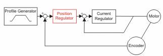
Pict. 1‑1 Controller structure for
positioning servo systems [1]
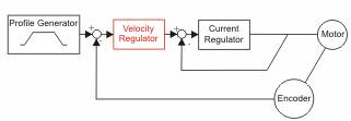
Pict. 1‑2 Controller structure for speed
servo system [1]
For
controller setting we used “Regulation tuning wizard” built in Epos Studio. In
both cases we have to tune the current regulator, then velocity or position regulator.
The tuning procedure is based on response of step or profile of current, speed
or position. The measure of controller performance is the summation of
deviations. The deviation is represented by Performance index; lower number
means lower deviations and better performance of controller.
For current
controller tuning we have to block the shaft of motor to make the back EMF
voltage equal zero. Block of the
shaft on small non-geared drive is not a problem. The proper setting of current
step is very important in case of using gearboxes. The current step means step
of torque equal current multiplied by torque constant. It produces jerk peaks.
In all cases check the maximal speed.
2
CURRENT
CONTROLLER SETTING
For current
controller setting we defined current step as a half of nominal current. For
self-tuning procedure it is better to use high current to reduce errors of
measurement.
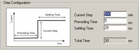
Pict. 2‑1 Current step definition
With several
runs of self-tuning procedure we reached setting in following table. The
starting point P gain and I gain was different for each run.
|
Performance
index |
P-Gain |
I-Gain |
|
8992 |
14 |
149 |
|
7344 |
250 |
186 |
|
6915 |
500 |
375 |
|
7293 |
799 |
300 |
|
8635 |
300 |
150 |
|
7293 |
375 |
224 |
|
6462 |
345 |
280 |
|
default
values |
400 |
200 |
Table 2‑1 Current controller self tuned
parameters
For
self-tuning procedure there must be defined a proper starting point, otherwise
the self-tuner can reach wrong setting, shown in line one. In the highlighted
lines there is shown, that almost the same performance can be reached by a very
different controller setting. The higher parameters in this case do not lead to
higher dynamic, but it leads to higher heating up the motor.
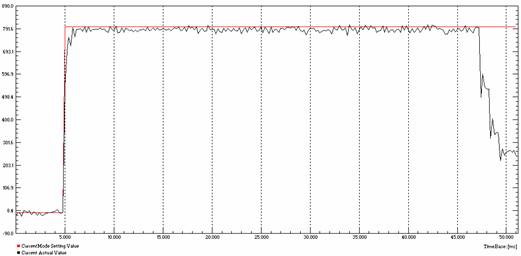
Pict. 2‑2 Fast step response of current
controller with no overshoot and small riple (time scale in ms)
3
SPEED
CONTROLLER SETTING AND VALIDATION
For speed
controller settings there is necessary to allow the free run of the shaft. If
we have to tune the parameters on machine with proper load or in other
mechanics, we will position the system to the half of positioning range and
modify the setting time and step size to stay securely in position range.
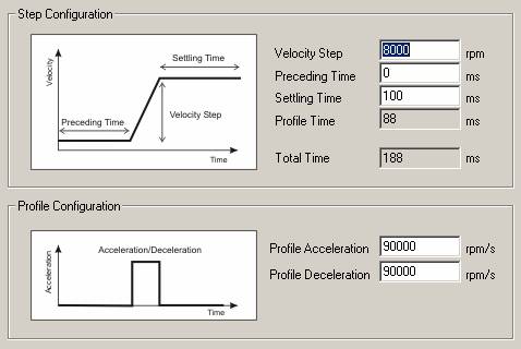
Pict. 3‑1Configuration of profile for speed
controller setting
During the
high performance tuning the response of system could be oscillating, so do the
precise tuning manually.
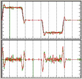
Pict. 3‑2 Response of system to profile
velocity step, first speed, second following error, overshoot in transient
states, oscillations in steady states, wrong parameter setting
The table
of results is shown in following below.
|
Performance index |
P-Gain |
I-Gain |
|
37696 |
1773 |
279 |
|
677277 |
1250 |
25 |
|
56991 |
3122 |
37 |
|
42342 |
3249 |
372 |
|
38529 |
1625 |
298 |
|
39822 |
2500 |
312 |
|
38109 |
2000 |
390 |
|
39392 |
1375 |
175 |
|
default |
400 |
100 |
Pict. 3‑3 Speed controller setting
However,
the performance index in not an absolute measure of the controller setting.
With lower velocity step we achieve lower performance index with the same
controller setting. For example for P-Gain = 1625 and I-Gain = 298 is for step
8000 rpm 38529, but for step 1000 rpm is only 24481.
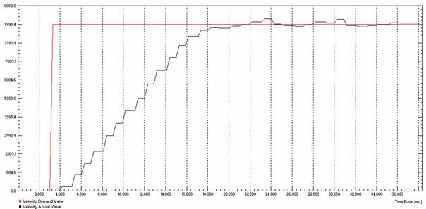
Pict. 3‑4 Response (black) of motor to step
of demand speed (red), time in ms, speed in rpm
The
response of velocity step is stable, with no overshoot and with quite good
dynamic.
4
POSITION
SYSTEM CONTROLLER TUNNING AND VALIDATING
The
position controller structure is slightly different from conventional
three-loop cascade, position, speed and current controller. The position
controller is PID and it controls the drive with internal PI current loop.
Therefore the tuning of position controller is harder than other systems.
Pict. 4‑1 Position step profile configuration
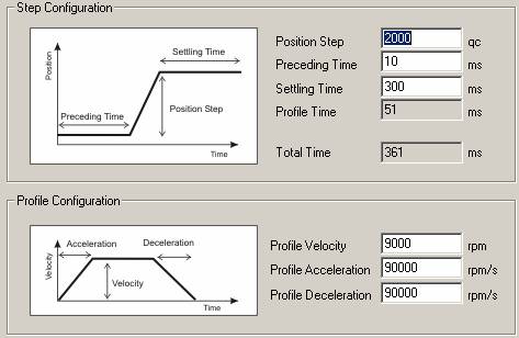
The
position autotuning needs free run shaft as well as speed controller. So we
have to modify the step size and the setting time according to positioning
range. With defined profile we achieved this controller self tuned parameters.
|
Performance index |
P-Gain |
I-Gain |
D-Gain |
|
1398 |
626 |
218 |
281 |
|
732 |
1375 |
347 |
337 |
|
647 |
1375 |
433 |
337 |
|
771 |
1492 |
444 |
364 |
|
679 |
1528 |
439 |
374 |
|
668 |
1375 |
325 |
337 |
|
default values |
150 |
10 |
200 |
Pict. 4‑2 Position controller tuning
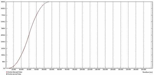
Pict. 4‑3 Profile position step response, red
position demand value, black position actual value, time in ms,
position in quad counts
We can see
very low performance index and very good response of the whole system. For high
dynamic of the position controller there is necessary to have as well a set
current controller.
In the
position controlling mode there is possible to use feed forwards. This feed
forwards could improve the dynamic response in case of high moment of inertia
on shaft. In our case there is not necessary to use them.
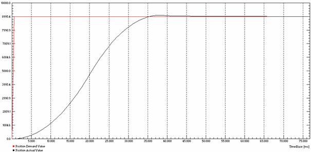
Pict. 4‑4 Position
control with feed forward, a little smaller overshoot
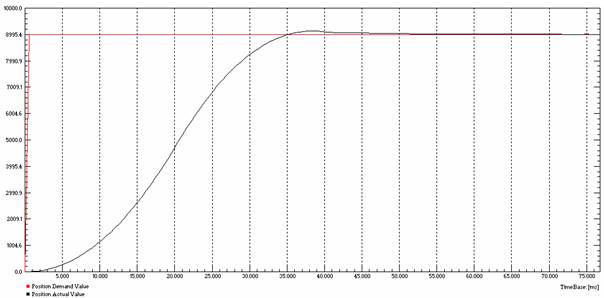
Pict. 4‑5 Position
control without feed forward, a little higher overshoot
In case of
low moment of inertia on shaft it is not necessary to use feed forwards.
5
CONCLUSION
The regulation-tuning
wizard is a good tool for proper controller settings. However, the user has to
pay attention to results of the tuning and have experience with reasonable
values of each controller.
To setting
the controller in mechanics we have to pay attention to range of movement and
modify the setting time and step size to reduce the movement.
The
comparison of two performance indexes is possible only if the indexes were
achieved with the same profile.