Engineering science
1Liyasova O.V., 1Polishchuk
V.I.
1National Research Tomsk Polytechnic
University, Tomsk.
DEVELOPMENT OF SHORT CIRCUIT OF COILS PROTECTION OF SYNCHRONOUS
GENERATOR ROTOR WINDINGS
Introduction. The short-circuit of coils in synchronous generator’s rotor winding is
widely-spread [1] and hardly amenable to control disrepair [2]. In view of some
design features, standard based revealing of the short-circuit of coils in
rotor winding is an intractable problem. The most promising ways are based on
the analysis of the external and internal magnetic fields of the synchronous
generator since the correctly functioning synchronous generator has a sustained
symmetric shape of a magnetic field distribution in the air gap, in the core
and around it. This shape contains information connected directly and
functionally with the technical state of the synchronous generator.
Installation of the special magnetic field sensor is required in order to
conduct the control of short-circuit of coils in the rotor based on the
magnetic field symmetry analysis.
It should be noted that for relay protection issues
it’s significant to detect the space structure destruction distribution level
of magnetic field caused by the winding, not the level of magnetic field components,
i.e. requirement for current changes of pole’s fields figures detection relative to each other.
There is
certain number of devices [3-5] containing an induction sensor, which is
installed in the air gap near the rotor’s surface. Installed this way the
induction sensor gains its maximum sensitivity since the
short-circuit of coils is being defined by the EMF pulse amplitude which are
depend on the total current in every pole’s coil slot. However induction sensor
placement in the air gap or near it significantly reduces synchronous
generator’s reliability because of the possibility of its contact with rotor
which inevitably will lead to generator’s breakdown. The sensor installed on
the high-powered synchronous generators should be able to withstand great windy
loads under conditions of two atmospheres pressure and flow rate equals to
50-100 meters per second. Besides, this sensor could be easily damaged during
the rotor’s removal due to the repair.
Problem
statement. The mission was to gain the short-circuit of coils
signs in synchronous generator’s rotor winding and to develop the protection
based on the dispersion magnetic field sensor installed in the synchronous
generator’s end.
Experimental
setup. The structure of the experimental setup is shown on fig.1.
Induction sensor was
used to measure the stray flux. It consist of the synchronous generator
with the pair number of poles p=1 (ГАБ-4-T/230 generator model) 1, which is being actuated by the
nonsynchronous engine supplied by the frequency transformer (Altivar 71) 9. For
making a short-circuit sealing-offs (3) (4%, 10% and 30% of the pole’s coil)
are taken out through the additional contact rings (2) of the rotor’s winding.
The induction sensor
(4) is installed on the synchronous generator’s end bracket. The signal
goes through the input connector (CB-68LP) (5) and IO-board (NI PCI 6024E, 12
bytes, maximum sampling frequency – 20 MHz, 16 analog outputs) (6) are released
through the industrial computer (7).
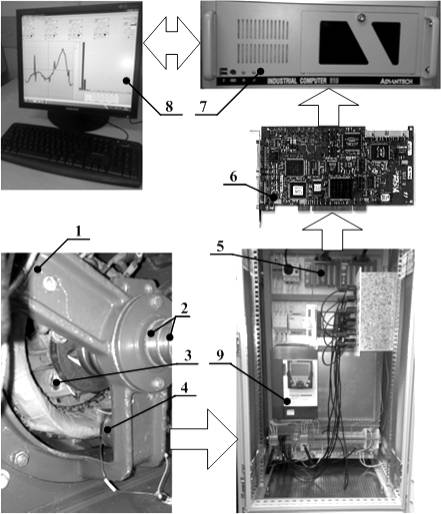
Fig.
1. Experimental setup
Fig. 2 shows the EMF experimental waveforms on the induction sensor’s output
under the condition of short-circuit in one of the two synchronous
generator’s poles (for
display purposes short-circuit is 30% of all coils number) during the
open-circuit (Fig.2a) and under the load (Fig.2b). Curve 1 marks waveform in
case of the short-circuit of coils in rotor winding, curve 2 – without
it. According to the waveforms, during the short-circuit of one of the rotor’s
poles negative and positive EMF waveform are not symmetrical. They differ in
amplitude and shape. Therefore, difference of the positive and negative EMF
waveform on the induction
sensor output may serve as sign of the short-circuit of coils in rotor
winding.
 a) b)
a) b)
Fig.
2. EMF waveform on the induction sensor’s output under short-circuit condition
in rotor’s winding pole.
a
– open-circuit mode; b –nominal load mode
Ways of
protection. Protection method is based on the
fact, that magnetic field induction in any point of the synchronous generator’s
end zone is formed by the stator’s and rotor’s winding currents, and
magnetomotive force of the all poles are equal in magnitude. During the full
rotor’s turn 2p equals in amplitude half-wave would appear when magnetomotive
force is converted in the unipolar electric signal. Magnetomotive force and
consequently magnetic field induction in the generator’s end zone would
decrease in the case of the short-circuit in one of the pole’s coils part. Then
at every full rotor’s turn one of the 2p half-waves would have smaller
magnitude in the unipolar signal. This would cause a harmonic wave with the ![]() where
where ![]() – is power frequency.
– is power frequency. ![]() magnitude is proportional to the
number of closed coils in rotor’s pole. If
magnitude is proportional to the
number of closed coils in rotor’s pole. If ![]() will exceed the established magnitude then a signal reporting about synchronous generator’s rotor winding damaging would appear. Or, in the
case of device functioning in the protection mode, would appear a signal
causing rotor’s field killing and generator’s disconnection.
will exceed the established magnitude then a signal reporting about synchronous generator’s rotor winding damaging would appear. Or, in the
case of device functioning in the protection mode, would appear a signal
causing rotor’s field killing and generator’s disconnection.
For the realization of method the device was
designed, structure of which is shown on the Fig. 2. The structures includes:
gage sensor; B1, B2 – are blocks of the unipolar signal shaping (rectifiers);
HPF – high-pass filter for the constant component suppression in the unipolar
signal; LPF1 – low-pass filter for the periodic component isolation by ![]() ; LPF2 – low-pass filter for the
input signal magnitude formation on Schmitt trigger; LPF3 – low-pass filter forming the
reference voltage (set point); NIST – non-inverting Schmitt
trigger.
; LPF2 – low-pass filter for the
input signal magnitude formation on Schmitt trigger; LPF3 – low-pass filter forming the
reference voltage (set point); NIST – non-inverting Schmitt
trigger.
In the case of
synchronous generator’s rotor winding damage induction sensor’s when proceed through B1 contains
desired signal in the form of the subharmonious frequency ![]() and also the pulsation frequency 2
and also the pulsation frequency 2![]() and the constant component, which are need to be suppressed. For
the Schmitt trigger correct functioning it’s necessary to compare the desired signal magnitude
with the induction
sensor’s signal magnitude. Constant post B1 component serves as the reference
voltage because it is proportional to induction sensor’s signal and by changing
amplification coefficient on LPF3 one can change setup’s magnitude.
and the constant component, which are need to be suppressed. For
the Schmitt trigger correct functioning it’s necessary to compare the desired signal magnitude
with the induction
sensor’s signal magnitude. Constant post B1 component serves as the reference
voltage because it is proportional to induction sensor’s signal and by changing
amplification coefficient on LPF3 one can change setup’s magnitude.
Isolation of
the subharmonious
frequency ![]() is made by the analog band-pass filter, which consists of HPF and
LPF1
is made by the analog band-pass filter, which consists of HPF and
LPF1
Fig. 3. Structure of the relay
protection device
Experimental testing. To except the multiple actuations
near the switch point, Schmitt trigger electric hysteresis magnitude is set on the 20% level.
To test the device settings it was given a test
signal. As it seen on the Fig. 4. Schmitt trigger actuates in parts II and IV which
represent short-circuit imitation of the 2% of coils. Delay of Schmitt trigger
actuation (about 2 cycles or 0.04 sec) is caused by the delay time in filters
functioning. Device itself functioned logically right.
Fig. 4. Device performance diagram
on the test signal example.
1 – post B1 test signal, 2 –
reference voltage, 3 – Schmitt trigger input voltage.
4 – Schmitt
trigger output voltage
After tuning by the test signal the device was tested
on the experimental synchronous generator. The device accurately detected of
short-circuit of coils in winding under the 4% pole’s coil short circuit.
Besides there were no fake actuation during power surge and drop modes,
initiation, non-symmetrical phases loading, earth fault in the one excitation circuit
point and earth fault of stator’s phase. Device actuation is restarted in
3-phase short-circuit mode on the outputs of synchronous generator, which
should be switched off immediately by its protection system. Introducing of the
time setup would except the fake performance of the developing protection.
Conclusion
1. The short-circuit of coils protection in synchronous
generator’s rotor winding causes the destruction of stray magnetic field
symmetry. Short-circuit can be detected by means of measuring and comparing the
level of stray magnetic field disorder
between the damaged and undamaged poles with the help of the special sensor.
2. EMF transformation in unipolar signal on the induction
sensor output with the following isolation of the subharmonious frequency equals the rotor’s turning
speed allows to detect the rotor’s short-circuit of coils.
3. As a result, during the experiments it was revealed
that developed device is able to detect the short-circuit of the 4% of coils in
in synchronous generator’s rotor winding.
References
1. Alekseev A.E., Kostenko M.P. Turbogenerators. – M:
Gosenergoizdat, 1939, - 341 p.
2.
Glebov I.A., Danilevic
JA.B. Diagnostic of turbogenerators. – L: the Science, 1989. – 119 p.
3.
How to diagnose and
control circuits in the rotor winding of synchronous machine: a stalemate.
2192649 dews. Federation. № 2000129947/09; Appl. 30.11.2000; in English. 11 Nov
2002
4.
Jackson R.J., Roberts
I.A., Thurston R.C., Worsfold J.H. Generator rotor monitoring in the United
Kingdom//CIGRE. – 1986. Report 11-04, 8 p.
5.
Samorodov JU.N.
Turbogenerators. Accidents and incidents. – M: ELEKS-KM, 2008. – 488 p.
Abstract. The new method of short-circuit of coils protection in synchronous
generator’s rotor winding is based on the induction sensor of stray magnetic
field. The relay protection device is developed and researched on the
experimental setup, the methodology of this device tuning is defined.
Key words: the synchronous
generator, a rotor winding, short circuit of coils, relay protection.