Строительство
и архитектура / 3.Современные
технологии строительства, реконструкции и реставрации.
D. Egn., Prof. Golovko S.I., graduate
Shekhorkina N.E.
State Higher Educational
Establishment «Prydniprovs’ka State Academy of Civil Engineering and Architecture»,
Dnipropetrovsk, Ukraine
Injectability analysis of cement grout with different
water-cement ratio in fine sand
Abstract. Soil stabilization has become one
of the useful solutions to treat the soft soils to achieve the required
engineering properties and specification so that structures can be placed
safety without undergoing large settlements. Numerous of grouting materials are
available in this field now. Cement is the most popular grouting material where
the strength improvement of the formation materials is the major concern. Fine
sand is known to be not suitable for the application of cement based grouting. The
efficiency of grouting mainly depends upon the penetration of cement grout
through the pores of sand. Study of the grout injectability with different
water-cement ratio in fine sand was carried out in the present research work.
The results clearly indicated that water-cement ratio of grout has influence
only on mechanical characteristics of sand after strengthening but practically not
on the injection radius.
Key words: grouting,
grouting setup, cement grout, water-cement ratio, fine sand, injection radius,
void ratio.
Introduction. Grouting for ground engineering is
a process of filling the voids, fissures or cavities existing in the soil to improve
water-tightness or mechanical characteristics by the grouting material. The use
of grouting has become more popular in the recent years due to rapid
development of sub-surface infrastructure, underground facilities and
underground space for commercial and civil defense uses and the need in ground
control during construction.
Grouting can be used to improve the condition of site against possible
construction problems, such as: to reduce permeability of soil for minimizing
seepage effect, to strengthen soils for improving its load carrying capacity,
excavation stability and resistance against liquefaction effect, to improve
stability of existing structures and to adjust profile of distorted structures,
to stabilize ground for facilitating tunneling or shaft excavation, to form a
barrier or cutoff the water or contaminant flow in the ground.
Three types of grouting materials are generally recognized:
suspension-type grouts, emulsion-type grouts and solution-type grouts [4, 5]. The
suspension-type grouts include clay, cement and lime, while the emulsion-type
grouts include bitumen and the solution-type grouts include a wide variety of
chemicals. The type of grout material involved in the present study belongs to
the suspension type of grout. Suspension is defined as small particles of
solids which are distributed in a liquid dispersion medium, e.g. cement in
water, and having a Bingham’s fluid characteristics.
In accordance with theoretical investigations [2] it
was established that fine to medium sand cannot be strengthen by cement based
permeation grouting in view of its small pore size and low permeability to
water. But Cambefor A. found that sand ground is suitable for cement fracturing
grouting [2]. This fact was confirmed by numerous practical researches made by
Golovko S.I. [1]. He investigated the process of strengthening the sand by
high-pressure cementation.
Although it is a well known fact that properties of
grout have great influence on injection results. Even today grouting operations
are based on thumb rules and existing practices rather than design principles
and well defined procedures substantiated by research data.
Aim of research. In this paper an attempt is made
to study the injectability of cement grout with different water-cement ratio in
fine sand.
Results and discussions. Ordinary Portland Cement the
properties of which are shown in Table 1 was used for the present study. The
sand used for the present study was collected from the sand pit near the
Dnipropetrovsk. The sand was sieved through a set of sieves and the fraction
between 0.1 and 1 mm (fine sand) was used for the experiments. The grain sizes
of this sand are shown in Table 2.
The grouting efficiency can be estimated by determination the injection
radius and the volume of the hardened grouted samples.
In the present research grouting tests were conducted under vertical
flow model where grout was injected vertically downward through sandy media in
a cylindrical tank with uniform cross-sectional area under constant injection
pressure for measurement of flow volume.
Table 1
Cement Properties
|
Sl. No. |
Property |
Characteristic value |
|
1. |
Standard consistency |
27.5% |
|
2. |
Initial setting time |
131 mts |
|
3. |
Final setting time |
287 mts |
|
4. |
Specific gravity |
3.14 |
|
5. |
Specific surface (blane’s) |
298500 mm2/g |
|
6. |
Compressive strength 7 days |
24.53MPa |
Table 2
Sand Grain size
distribution
|
Characteristic value |
Sieve analysis |
Results of grain size distribution |
|||
|
Ground fraction, mm |
|||||
|
from 1 to 0,5 |
from 0,5 to 0,25 |
from 0,25 to 0,1 |
less then 0,1 |
||
|
Weight of
ground sample, g |
860,6 |
fine sand |
|||
|
Weight of
ground fraction, g |
7,32 |
142,14 |
687,48 |
23,66 |
|
|
Fraction loading, % |
0,85 |
16,52 |
79,88 |
2,75 |
|
The grouting setup consists of a grout chamber, membrane pump with pressure-gauge,
cylindrical ground tank, grouting nozzle and high-pressure hoses. General view
of grouting setup is shown in fig. 1.
The cylindrical ground tank of 500 mm in high and 500 mm in diameter had
a lower and an upper clamp covers. Dimensions of ground tank and grouting
nozzle were determined according to the similarity theory and dimensional
analysis [3]. Table 3 shows values of injection process parameters in nature
and in model where the scale parameter (λ) of 0.2.
Fig. 1. General
view of grouting setup: 1 – grout chamber; 2 – membrane pump; 3 – ground tank;
4, 5 – high-pressure hoses; 6, 9 – stopcock; 7 – pressure-gauge; 8 – grouting
nozzle;
10 – sand bed;
11 – perfectly elastic material; 12 – upper clamp cover.
Table 3
Parameters of
injection process
|
Parameters of cementation |
Value in nature |
Value in model (λ=0.2) |
|
Diameter of grouting
nozzle d, m |
0.093…0.127 |
0.02…0.025 |
|
Pressure of injection P, MPa |
0.5…1.5 |
0.22…0.67 |
|
Radius of injection r, m |
0.78…1.5 |
0.11…0.24 |
Sand bed was prepared at the loosest unit weight of 13.4 kN/m3
and the initial void ratio (emax) of 0.98. The layer of perfectly
elastic material was situated between the sand daylight and the upper clamp
covers and designed the stresses from the dead weight of sand in natural
conditions. If the sand average unit weight (γ) of 15 kN/m3 the
stresses from the sand dead weight (σzg) are 45 kPa at the
injection deep of 3 m. In accordance with this fact and compressive test the
level of perfectly elastic material must be higher than the wall of ground tank
of 8 mm for modeling the natural conditions. Grouting nozzle was situated in
the central part of ground tank. There are perforations in the middle of
grouting nozzle for the flat-radial filtration of solution.
The grout was suspension-type and consisted of cement and water. Grout
was prepared at water/cement ratio (W/C) of 0.5 and 1.0 and agitated well to
get uniform grout solution which was poured into the grout chamber. In order to
reduce the chances of the grout segregation, an agitator was provided in the
grout chamber. Grout volume for injection is 7 liters. Grout was pumped under a
uniform pressure of 4 atm into the prepared sand bed. During the process of
cementation spill water was released from the solution because of injection
pressure. There is an additional damping and therefore compaction of sand bed. The
grouted samples were kept in the ground tank during 3 days for curing. General
views of sand bed after cementation are presented in fig. 2. Typical
photographs of grouted sample are shown in fig. 3. Characteristics of grouted
samples are shown in table 4.
|
a) |
b) |
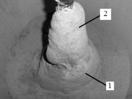
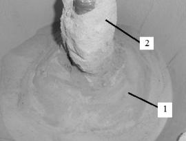
Fig. 2. General
view of sand bed after cementation: a – W/C=0.5; b – W/C=1.0;
1 – damping
zone; 2 – cement stone.
|
a) |
b) |
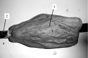
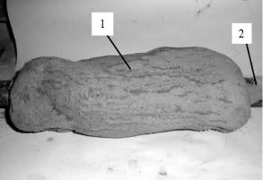
Fig. 3. Typical photographs of grouted samples: a – W/C=0.5; b – W/C=1.0;
1 – cement stone; 2 – grouting nozzle.
Table 4
Characteristics of grouted
samples
|
Characteristic value |
Grouted samples |
|
|
W/C=0.5 |
W/C=1.0 |
|
|
Diameter, mm |
150 |
120 |
|
Length, mm |
270 |
310 |
|
Density, g/cm3 |
2.064 |
2.191 |
|
Mass, g |
4150 |
3685 |
|
Volume, cm3 |
2010.66 |
1681.9 |
|
Compressive strength, MPa 3 days |
35.61 |
36.34 |
During injection there is a drilling grout loss of 3 liters in the
grouting setup. Therefore only 4 liters of grout were injected in sand bed. According
to the elementary mathematical analysis water absorbing is 2 liters for grout
with W/C=0.5 and 2.32 liters for grout with W/C=1.0.
It can be seen from the table 4 that application of grout with W/C=0.5
is more effective. Such grout causes the bigger injection radius and therefore
indicates better flow of the grout in the lateral direction.
Samples of ground from different depths were cut from the grouted mass
for the determination of soil dampness and consistency. Table 5 shows the
variation of sand bed properties with injection depths of 100, 200 and 400 mm
from the top of the grouted bed.
Table 5
Characteristics of grouted
sand bed
|
Depth of injection, mm |
Grouted sand bed |
|||||||
|
W/C=0.5 |
W/C=1.0 |
|||||||
|
ρ, g/cm3 |
ρd, g/cm3 |
W, % |
e |
ρ, g/cm3 |
ρd, g/cm3 |
W, % |
e |
|
|
100 |
1.548 |
1.458 |
6.2 |
0.82 |
1.681 |
1.594 |
5.5 |
0.66 |
|
200 |
1.598 |
1.501 |
6.5 |
0.76 |
1.651 |
1.542 |
7.1 |
0.72 |
|
400 |
1.597 |
1.531 |
4.3 |
0.73 |
1.59 |
1.513 |
5.1 |
0.75 |
There are better properties of sand bed for injection of grout with
W/C=1.0 because it has higher water content. But lesser values of consistency
and void ratio of sand bed after injection of grout with W/C=0.5 is compensated
by bigger injection radius.
Conclusions. The
efficiency of grouting mainly depends upon the penetration of cement grout
through the pores of sand. The following conclusions are drawn from the results
of injection radius determination on samples from the
grouted mass, in order to assess the quantum of grout lateral flow into the
sand soil. Cement grout with W/C=0.5 is more effective in fine sand compared to
grout with W/C=1.0, while considering the travel distance of the grout and the
properties of soil at various points in the grouted mass.
Thus, the present study undoubtedly proves the importance of
water-cement content selection in grout to achieve the largest injection radius
and effective strengthening of soil.
References
1.
Головко
С.И. Теория и практика усиления грунтовых оснований методом высоконапорной
цементации: Монография. / С.И. Головко. – Днепропетровск: Пороги, 2010. –
247 с.
2.
Камбефор
А. Инъекция грунтов. Принципы и методы / А. Камбефор; [пер. с фр.
Р.В.Казаковой, В.Б.Хейфица]. – М.: «Энергия», 1971. – 333 с.
3.
Седов
Л.И. Методы подобия и размерности в механике / Л.И. Седов – М.: Наука, 1977. –
440 с.
4. Beker W.H., Huck P.J. & Walter M.I. Design and control of chemical
grouting. Construction control / Beker W.H., Huck P.J. & Walter M.I. // –
Washington: DC, 1982. ‑ Vol.1. – 320 p.
5. Mitchell J.K. Soil improvement/ J.K. Mitchell // State of the Art
Report. ‑ Stockholm: Sweden, 1981. – P 509-565.