Issakhov
A.A., Abdibekov U.S., Zhubat K.Zh.
(al-Farab Kazakh National University, Almaty,
Kazakhstan)
NUMERICAL SIMULATION OF THE ROCKET FUEL COMPONENTS PROPAGATION IN THE STRATOSPHERE DURING THEIR DRAINAGE ON THE 1-ST STAGE OF LAUNCH VEHICLE
Phenomena developing in the stratosphere at altitudes of 40-50 km related to emissions from residual fuel components after separation of the first stages of launch vehicles, in addition to depletion of the ozone layer, cause greenhouse effect. It should be noted that the first stage of the launch vehicles rises to heights of 45 - 50 km and the total weight of the fuel ejected by drainage into the atmosphere is 0,1 – 0,5 t. The characteristic features of such structures development are the relatively small rate of their expansion determined by the diffusion and wind delivery. These features are primarily defined by physical conditions in the development of these phenomena as well as by composition and quantity of the injected substances into the atmosphere. The importance of research of this type of phenomena first of all is connected with the need to assess the potential level of the environment contamination.
The subject of this paper study
is to stimulate the propagation of fuel in the drainage of the first stage of the launch vehicle. Knowing the amount of spent fuel in the atmosphere it is possible to
stimulate the dynamics of its further spreading. The dimensions of the cloud are
determined by the amount of spilled fuel, the time since the beginning of the
cloud formation and the properties of the environment. The phase of dynamics
movement and transformation of the aerosol cloud in fact is the subject of the mathematical simulation.
1. Mathematical
model. Large-scale
motions in the stratosphere are approximately described by a system of
equations including the equations of motion, continuity equation and the
equation of concentration. We
consider the development of spatial turbulent stratified atmosphere.
 (1)
(1)
 (2)
(2)
where ![]() (3)
(3)
The three-dimensional model of the transfer
of an active impurity in the stratosphere is used to simulate the propagation
of the combustion products of rocket fuel in the ozone layer
 (4)
(4)
ui – velocity components, D – diffusion coefficient, ![]() .
.
The Smagorinsky
dynamic model is used as a turbulent model. To use the dynamic model, a double
averaging is carried out with the length of filter![]() , then
, then
 (5)
(5)
Equation
(1) subjected to averaging with two
filters with length of ![]() and
and ![]() respectively, looks as follows:
respectively, looks as follows:
 (6)
(6)
where ![]() ,
,
from
(5) and (6) follows ![]() , then
, then ![]() takes the following form:
takes the following form: ![]() ,
,
and Leonard
voltages look as: ![]() (7)
(7)
From
(7) in using the method of least squares is evaluated ![]() in the form of
in the form of  ,
,
where ![]()
For the unsteady three-dimensional equation of motion, continuity and
concentration are determined the initial and boundary conditions satisfying the
equations.
2. Numerical algorithm. The numerical solution of (1) - (4) system
is carried out on a staggered mesh using the scheme against the flow of the
second type and compact approximation for the convective terms [1-5]. A splitting scheme by physical
parameters is used to solve the problem, by taking into account the above
proposed model of turbulence. In the first stage it is expected that the transfer
of kinetic momentum is carried out only by convection and diffusion.
The intermediate velocity field
is found by method of fractional steps by using a double-sweep method. In the
second stage, a pressure field is found by a determined intermediate velocity
field. The Poisson's equation for pressure field is solved by Fourier method in
conjunction with the method of matrix double-sweep, which is used to determine
the Fourier coefficients [6]. In the third stage it is assumed that the transfer
occurs only due to pressure gradient. The problem algorithm is parallelized on high-performance
system.
I) ![]()
II) ![]()
III) ![]()
3. The results of numeric simulation. For a detailed study of the stratosphere contamination, the problem is
solved in the presence of a cross-flow side air streams in the middle atmosphere.
To solve the problems initial and boundary conditions and the amount of spent
fuel of the first stage of the launch vehicle were given. The mesh size 100х100х100 was
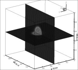
used in calculations. In Figures 1-2 are shown the fragments of
the RFC concentration distribution in the sections
after drainage of the first stage of the launch vehicle at different
times. The height of drainage is 50 km with the
following wind at speed of 2 m/s. The
received results show that the concentration of combustion products is
distributed over a larger area than the dynamic field of disturbance. In the course
of time the dynamic field damps out and the field of concentration goes into a condition
of passive impurity and for long migrates in the stratosphere. To trace the further path of concentration
in the stratosphere after their transfer from the computational domain is also
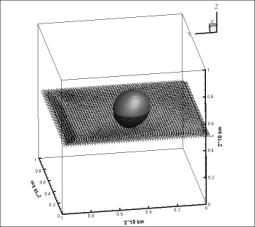
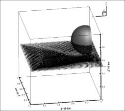
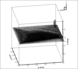
problematic, as it would require stimulation of large scales. Figures 3-6 show isosurface of RFC concentration distribution and field of
velocities in different times on a horizontal plane relative to the earth’s
surface. The drainage height is 50 km with side winds at speed of 3 m/s.
|
Figure 1- Distribution of the RFC concentration
in the sections in 1 hour after the drainage of the 1-st stage of “Proton-M” LV. The height is 50 km, the
following wind, speed of wind is 2 m/c. |
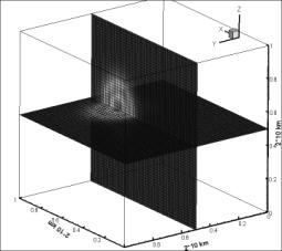
Figure 2- Distribution of the RFC concentration
in the sections in 4 hours after the drainage of the 1-st stage of “Proton-M”
LV. The height is 50 km, the following wind, speed of wind is 2 m/c. |
|
Figure 3- Isosurface of the RFC concentration and field of velocities in 1
hour after the drainage of the 1-st stage of “Proton-M” LV. The height is 50
km, side wind, speed of wind is 3 m/c. |
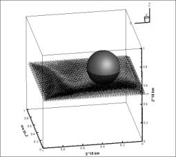
Figure 4- Isosurface of the RFC concentration and field of velocities in 3
hours after the drainage of the 1-st stage of “Proton-M” LV. The height is 50
km, side wind, speed of wind is 3 m/c. |
|
|
|
REFERENCE
1. Fletcher K. Computational methods in fluids dynamics. In 2 volumes: V.2.
– M.: Mir (World), 1991–552 p.
2. Rouch P.
Computational fluid dynamics. – M.: Publishing house “Mir” (World), 1972. – 612
p.
3. Tolstykh A.I. Compact
difference schemes and their application in the aerohydrodynamics problems. –
M.: Nauka (Science), 1990. – 230 p.
4. Pairaud R., Taylor
T. Computational methods in problems of fluid mechanics. –L.: Gidrometeoizdat,
1986.-352p.
5. Yanenko N.N. The methods of fractional steps for
solving multidimensional problems of mathematical physics. Novosibirsk:
Nauka (Science), 1967.
197 p.
6. Samarsky A.A.,
Gulin A.V. Numerical techniques. – M.: Nauka (Science), 1989. –432p.