Kulyk A.Y., Polic
A. A.
Vinnitsia national
technical university
Adaptation of the device
transmitting information to the parameters chennel in terms of its
unsymmetrical
for control and measurement
system
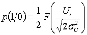
The
main problem during the transfer of information is that increasing the
probability of requiring speed reduction transmission, and reduces the
possibility of increasing the speed [1 ,2]. During the analysis of
communication channels is that channels are symmetric, ie the probability of
distortion of zeros and ones in the communication channel p (0 / 1) and p (1 /
0) are the same. Accordingly, the chart looks like the signal levels is shown
in Fig. 1, a threshold level identification signal is set at half its
amplitude.
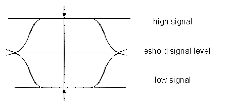
Fig. 1.
Diagram of signal levels for symmetric communication channel
However,
in real systems and networks more often asymmetrical channels for which the
conditional probability distortion symbols p (0 / 1) and p (1 / 0) unequal.
Given the large number of factors influence analytically calculate the numerical
values of these probabilities is difficult. Consider symmetric channels means
immediately enter methodological error, worsening terms of the identification
signal.
The
positive effect is testing transmission channels sequences of zeros and ones
with the definition of probabilities and the determination of optimal threshold
levels identify logical "zero" and "unit Because to date to facilitate the analysis of
communication channels was assumed that they are symmetrical, then this task is
not put into practice and not considered for theoretical studies, although it
is very real for unipolar transmission mode. For bipolar mode, these
probabilities are converted to the probability of errors of the first рІ and рІІ second kind.
Given
the large number of independent factors that affect the signals during their
formation, transfer, recovery and identification, it is highly likely to be
considered, the voltage signal in the communication channel is a random variable
with normal distribution. It centered on U, when transmitted "one",
and to 0 when transmitted "zero" for the first case under
consideration or under when transmitting an information signal and in his
absence for the second case. Therefore, conditional probability of receiving a
symbol "0" when transferred to "1" equals the probability
that the voltage at the input of the receiver is below the threshold of Us. The
expression for this probability will be:
 .
(1)
.
(1)
Similarly,
the conditional probability of receiving a symbol "1" when handed
over to "0" will be:
 . (2)
. (2)
Substitution
variables can get the formula:
 , (3)
, (3)
 . (4)
. (4)
If an
asymmetric channel, the conditional probability distortion character data for
the specific conditions of transfer are related:
![]() .
(5)
.
(5)
Then,
taking into account formulas (5.46) - (5.49)
 (6)
(6)
From
the expression (5.51) can be obtained
U - Us = ![]() × Us (7)
× Us (7)
![]() , (8)
, (8)
where U
- the amplitude of the signal in the communication channel.
Because
of the same communication channel ratio will vary depending on the speed of
transmission, signal amplitude, etc., then the test channel, you must perform
in those conditions that will be implemented to transmit informative data.
Based
on the foregoing, the implementation of this method requires the adaptation of
a list of actions:
-
allocate a channel of communication through the serial interface and modem
binary test sequence;
-
accept from a selection of system test results communication channel;
- read
from the media PC data to be transmitted;
-
transfer in sequential code to interface data;
at the
receiving side:
-
obtained from the channel of communication via modem and serial interface
binary test sequence;
-
determine the coefficient unsymmetrical communication channel according to
formula (6);
-
calculate the threshold level identification signal according to formula (8);
- pass
on the transmission side of the results, which indicate the end of the first
stage;
-
determine in accordance with the speed of transmission time intervals
identification of informative signals and record them in a timer;
-
measured at fixed intervals voltage levels in the communication channel;
- read
measurement information;
-
compare with the specified voltage threshold level and identify the level of
the signal;
- write
the information to the media PC.
Implement
this method using classical micro structure [2]. In this case, the proposed
mode survey software channels, although the implementation can be done with
certain changes and for any other.
Scheme
of the device shown in Fig. 2.
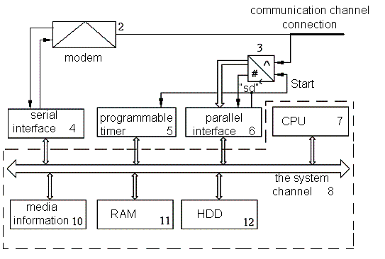
Fig. 2.
The structure of the device implementation method adaptive information transfer
When
you turn the power on the transmission of the CPU 7 personal computer 9
performs the initialization of the device so that the serial interface 4
programmatically configured to set the transmission speed information channel C
parallel interface 6 - for output, and channels A and B - on data input,
programmable timer 5 is configured to interrupt the terminal mode counting.
The
first stage is testing a communication channel, for which it via serial modem 4
and 2 passed the test sequence of "zeros" and "units" that
are at the receiving side of the modem 2 arriving on serial interface 4.
The CPU
7 9 PC reads data from serial interface 4 and writes them to the operational storage
units 11, and then calculates the ratio unsymmetrical channel according to
formula (5.50).
According
to formula (5.53) calculate the optimal value of threshold voltage
identification signals Us, that the real value of noise in the communication
channel 1. These results are transmitted to the transmitting part, which
indicates the completion of testing communication channel 1. At the second
stage of the CPU 7 9 PC reads data bytes from the storage medium 10 and by a
serial interface 4 and 2 modem transmits them to the communication channel 1.
On the
receiving side, based on the speed of transmission time intervals calculated
levels of identification signals from the communication channel 1. To counter
the programmable timer, 5 recorded a number that is calculated by the formula:
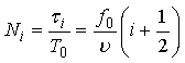 ,
(9)
,
(9)
where f0
- clock frequency programmable timer counter 5;
τi
- i-th time interval identification signal communication channel 1;
υ
- speed transmission of information communication channel 1.
The
first high level voltage signal coming from a communication channel indicates
that it will come after zero bytes and information. Controlling time intervals
identification data by using the programmable timer 5 in reading mode "on
the fly." When the counter value in Ni is launched analog-digital
converter 3 by a signal "Start" channel through C parallel interface
6. The signal "End of conversion" that comes from analog to digital
converter channel 3 on a parallel interface 6, shows the complete measurement
of the current value signal Ui and install the channel A parallel interface 6
voltage value in digital form:
 . (10)
Observed
values of the signal is compared with threshold Ui Us and
identified as "zero" or "unit" depending on the amplitude.
Local cycle continues until the eight informative bits of bytes will not be
identified, then the data byte written to the operational storage units 11 PC
9.
The
process continues for as long as all information will be obtained, after which
it is written to the storage medium 10 PC 9.
The
method was tested during the implementation of the NTB, as well as at
"Navionika", "VinnytsyaHaz" and bank
"Petrocommerce-Ukraine".
The
method will be implemented based on the MSP430 microcontroller developed by
Texas Instruments. This is due to the fact that the microcontroller (MC) MSP430
made on the basis of 16-bit RISC LAC with 27 instructions and 7 addressing
modes, peripherals and flexible synchronization. Power controller connected
tires and tire data address the total Fon-neymanovskoyi memory (MAB and MDB
respectively). Combining modern CIE with modular analog and digital peripherals
on MSP430 MCUs orients mixed signal processing applications. MSP430 is a very
economical MK, because they are widely distributed in the 8 - and 16 bit
measurement applications with battery powered.
References:
1.
Кулик А.Я. Адаптація
пристрою передавання інформації до параметрів каналу в умовах його
несиметричності / А.Я. Кулик // Вестник Херсонского государственного
технического университета. – 2004. – № 1 (19). – С. 418 – 422.
2.
Патент
71202А України, МПК7 Н03М 13/00. Спосіб передавання дискретної
інформації з адаптацією до умов передавання та пристрій для його реалізації /
Кулик А.Я. (Україна); ВНТУ. – № 20031210868; заявл. 01.12.2003, опубл.
15.11.2004, Бюл. № 11. – 7 с.
3.
MSP430x2xx Family User’s Guide - Austin: Texas Instruments Incorporated, 2008 – 693c.
4.
Микроконтроллеры MSP430 компании Texas Instruments c Flash-памятью [Електроний ресурс]: (Казус) – Режим доступу: http://www.e-tools.info/
index.php?page= component_detail&id=10880
5.
MSP430FG4618 - описание
[Електронний ресурс]: (Компэл) – Режим доступу: http://mcu.compel.ru/mcu/MSP430FG4618IZQW
6.
Программирование через
интерфейс JTAG [Електронний ресурс]: (Рынок микроэлектроники) – Режим доступу: http://www.gaw.ru/html.cgi/txt/doc/micros/ avr/arh128/19_3.htm