Kulyk A.Y.,
Svyetlov A.V.
Vinnitsia national
technical university
The adaptation of transmission system to the
parameters of communication channel with defining of speed transmission and
power signals
In distributed
computer systems and networks of different functional purpose of information is transferred in very harsh conditions
of impacted noise. Due to this, in the communication channels are available distortion
and a form of signal at the output channel is different from its form at the entrance
(Fig. 1).
When the
signal sends to the receiving part, their identification is provided on a threshold
or transition through zero. As a result, the fronts signals at the channel output
does not coincide with the fronts of initial pulses at its input. Therefore, there
are marginal signal distortion that can lead to loss of information due to violation
of sync. The time distance between the fronts initial and final moment associate
with the nature and level of noise and at a certain speed transmission it will cause
to distortion of information.
Voltage
at the receiving side of the communication channel ![]() is the sum of voltages informative signal on the
transmitting side
is the sum of voltages informative signal on the
transmitting side ![]() and the noise
and the noise ![]() [1].
[1].
![]() .
(1)
.
(1)
The
difference in time between the fronts of pulses on transmission and receiving
side is characterized by transitions through zero signals under the defined
conditions![]() and
and![]() .
.
Fig. 1.
The distortion of signals during their transmission through the
channel of communication
Take into
consideration that displacement fronts
![]() (2)
(2)
is a little,
can be determined
 . (3)
. (3)
Based on
this
 . (4)
. (4)
As ![]()
![]() . (5)
. (5)
Substituting
the result into (2) you can get
 , (6)
, (6)
so the fact
that derivatives can be considered approximately equal,
 , (7)
, (7)
rapidity
of pulse fronts will be:
 . (8)
. (8)
where  – rate
of growth front.
– rate
of growth front.
Then
 . (9)
. (9)
Transmission
speed of signals communication channel υc associated with transmission of information
υі by the relation:
 .
(10)
.
(10)
Degree of
limiting distortion of pulses is determined by the relation
 .
(11)
.
(11)
Then
 . (12)
Based on
the fact that during the transmission in the communication channel by interaction
of several factors that are random and independent from each other, we can assume
that the resulting distribution law will be closer to normal
 . (13)
The distribution
density of a random variable f(δ) can
be found in (13) using the known expression [2]
 , (14)
 , (15)
 . (16)
Substituting
(15) and (12) to (13) you can get:
 . (17)
Based on
the obtained expression, standard deviation degree of limit distortion of pulses
is determined by the relation:
 . (18)
Obtained
formula (18) includes the speed of information transfer and the difference between
voltage levels of logic "1" and "0", i.e. parameters that can
vary during transmission. Based on the rule “3σ”, which shows that 99.7% of
values are included to the interval [3], you can choose the optimal speed transmission
υi and signal levels U1
and U0, getting limit pulse distortion
δ under the conditions maintaining the transmission efficiency of the device.
So the ultimate formula will look like:
 , (19)
 . (20)
Thus, based
on the known transmission parameters (for
example, amplitude levels of logical "0" and "1", rapid fronts),
upon defining the amplitude noise in the communication channel and error, you can
get a maximum speed of transmission for real conditions.
Based on
the foregoing, for the implementation of this adaptation method is necessary to
act in the following order: at the transmitting side:
-
to register values array of voltage noise in the channel of communication;
-
to calculate result of average noise voltage;
-
to determine the maximum baud rate using the formula (20) under the sacrificing
device performance and the necessary level of logic "zero" and "one"
transmission signals;
-
to select the default speed of information transfer;
-
to transfer terms of connection to the receiving side;
-
to read from the media PC information which can be transmitted;
-
to transfer in sequential code data through the interface with a defining
speed;
-
to convert signal by modulator according to defining levels of logic signals
and transfer it to the communication channel;
at the receiving
side:
-
to get through the communication channel conditions of information transmit;
-
to set the serial interface at a certain speed of information interchange
and a programmable voltage divider of a fixed coefficient with accounting of signal
attenuation in the communication channel;
-
to get from the communication channel information signals, to convert them
according to the coefficient by programmable voltage converter, then to demodulate
them;
-
to convert information from the serial interface format to parallel one;
-
to read information in parallel format from serial interface;
-
to write the information to the storage of a personal computer.
The described
sequence [4] can be realized by software and hardware way based on personal computer
or microprocessor controller. It can be used one of the following modes: software
survey, interrupt or direct memory access (DMA). The simplest case is a software
survey [5].
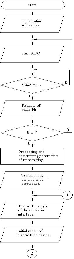
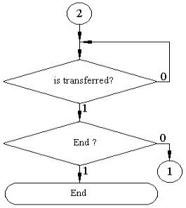
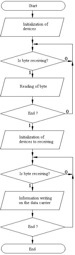
Scheme of
the device shown in Fig. 2, and schemes of work in the modes of transmitting and
receiving in Fig. 3 and 4.
Fig. 2.
Structure for implementation of the adaptation algorithm
When you
turn the power on the transmitting side the central processor 11 of the personal computer 9 it performs initialization devices, the serial interface 6 programmatically adjusted to the minimum speed of information transfer,
the channel of first 7 and channel of
C second 8 of the parallel interfaces - to data output, and channels A and B of second parallel interface 8
– to data input, amplification factor of a programmable amplifier 2 to establish equal to one.
 ,
,