Department of production systems and robotics,
Faculty of Mechanical Engineering, Technical University of Košice
Ing. Jaroslav ILEČKO
The simulation of human gait in Solid Works.
Annotation: This article shows the simulation of human gait in Solid Works
software. The goal of this project was to create simulation of human gait, so
it would be possible to gain relevant knowledge about torque moments needed to
move with every single joint of simplified human body. Sequence of this project
was following – first the simple human body was created, after then joint
actuators were added and the parameters of simulation were set. After this,
simulation was created and values of torque moments were gained.
1. Creation of human body in Solid Works.
To create virtual human body, the dimensions
of human body parts must be known. This information can be found in ergonomics.
Average proportions of man and women are shown on figure 1, 2 and in chart 1
[1]. The percentage value in chart 1 shows, how many % from whole human height
accrues to part of the body.
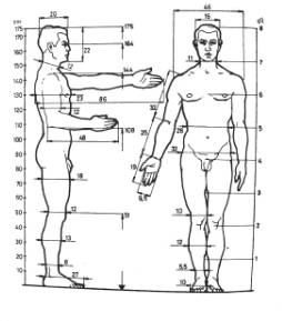
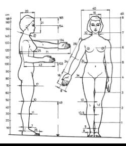
Fig. 1 Dimensions of human body
Fig. 2 Schematic figure for chart 1
|
|
|
Man |
Woman |
||
|
cm |
% |
cm |
% |
||
|
A B C D E F G H J K L M N O P R S T U V X Y Z |
Body
height Eye
height Arm
height Elbow
height Knee
height Hand
range width Extended
hand length Bent
forearm length Arm
width Chest
height Hip
width Body
height above seat Eye
height above seat Arm
height above seat Elbow
height above seat Back –
knee distance Lower
leg part length Hamstring
height Leg
height while sitting Foot
length Foot
width Hand
length Hand
width |
175 164 144 108 51 186 86 48 46 23 32 90 79 60 23 61 48 45 13 27 10 19 9,5 |
100 94 82 62 29 106 49 27 26 13 18 51 45 34 13 35 27 26 7,5 15,5 5,7 11 5,5 |
165 154 134 103 49 165 71 43 40 25 34 84 73 54 21,5 56 46 43 14 25 9 17,5 8 |
100 93 81 62 30 100 43 26 24 15 21 51 44 33 13 34 28 25 8,5 15 5,5 10,5 4,8 |
Chart. 1 Average dimensions of
human body parts
By
using this information, the virtual human body was created, figure 3.

Fig. 2
Virtual human body
After the body was created in correct size
and dimensions, to every part of the body was added its weight. Two
researchers, Mr. Zaciorsky and Mr. Selujanov [2], made the research for
specifying the human body segments weight. They experimentally measured 100
people with radioisotope method and specified indexes B0, B1 and B2 for every
part of the body – segment. For every segment is valid:
m i
= B 0 + B 1 m + B 2 v
where m is the whole human body weight and v is height in cm.
Also the position of centre of gravity was
specified. The whole segments length are measured from proximal end (closer to
center of body). Experimentally specified indexes are shown in chart 2.
Chart 2 Body segment weight
Segment |
B0
(kg) |
B1 |
B2
(kg.cm-1) |
Center
of gravity (%) |
|
Head + neck |
1,2960 |
0,0171 |
0,0143 |
50:50 |
|
Trunk |
|
|
|
42:58 |
|
Trunk – upper part |
8,2144 |
0,1862 |
-0,0584 |
|
|
Trunk – middle part |
7,1810 |
0,2234 |
-0,0663 |
|
|
Trunk – lower part |
-7,4980 |
0,0976 |
0,04896 |
|
|
Leg |
-2,6490 |
0,1463 |
0,0137 |
43:57 |
|
Shank |
-1,5920 |
0,03616 |
0,0121 |
41:59 |
|
Foot |
-0,8290 |
0,0077 |
0,0073 |
|
|
Upper arm |
0,2500 |
0,03013 |
-0,0027 |
44:56 |
|
Fore arm |
0,3185 |
0,01445 |
-0,00114 |
43:57 |
|
Hand |
-0,1165 |
0,0036 |
0,00175 |
39:61 |
By using this chart, weight of segments was
computed and set for 80 kg heavy and 175 cm tall man. By using Solid Works Mass
Properties, whole body weight was counted and the position of centre of gravity
was shown (violet dot on fig.4)
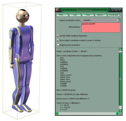
Fig. 4 Virtual body mass properties
2.
Human gait kinematics
The kinematics of human gait in basic
principle is possible to apply for every human, because in majority, the
construction of human body is the same. For simplification is the gait shown in
one period, fig.5 [3].
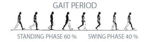
Fig. 5 Gait period
This gait period was measured, so every particular
angle of hip, knee, ankle, arm and elbow were known. This information was used
for creating the chart 3 of swing angle of every body segment.
Chart 3 Swing angle of body segments
|
Time |
Swing angle |
|||||||||||||||||||||||||||||||||||||||||||||||||||||||||||||
|
Left hip |
Right hip |
Left knee |
Right knee |
Left arm |
Right arm |
|||||||||||||||||||||||||||||||||||||||||||||||||||||||||
|
|
|
|
|
|
|
||||||||||||||||||||||||||||||||||||||||||||||||||||||||
The starting angle is 0 degrees, time 0
seconds. That is because the virtual man is beginning his movement from basic
position, when standing straight. Solid Works during simulation uses value of
swing angle and time value to move corresponding body segment from its actual
position to next position, in consequence with swing angle value.
Because angle of every segment at 0 second
is 0 degrees, the gait period as shown on fig. 5, starts at 2 second of
simulation and ends at 14,1 seconds.
After simulation frames of human gait
simulation were created. On fig.6 is selection of 8 frames that corresponds to
time values in chart 3.
|
|
|
|
|
|
|
|
|
|
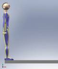
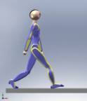
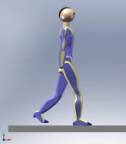
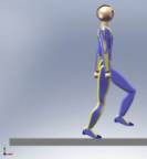
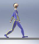
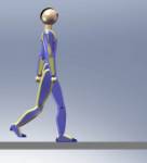
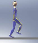
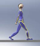
Fig. 6 Frames of human gait
3.
Results of simulation
After
the simulation, magnitudes of torques of every joint were generated, fig. 7.
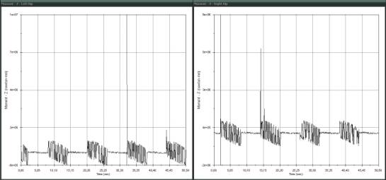
Left and Right Hip
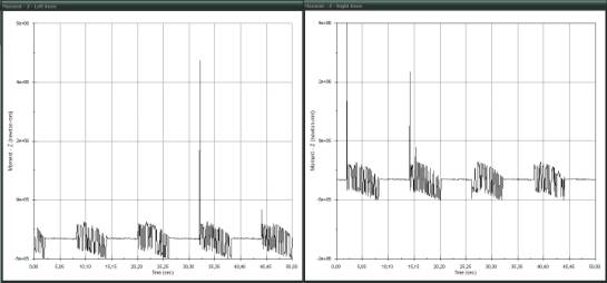
Left and Right Knee
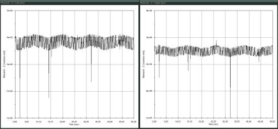
Left and Right Arm
Fig. 7 Hip, Knee and Arm Moment Magnitudes Diagram
In figure 7 are shown torque moments during
whole simulation, total time is 50,5 seconds. The periodicity of human gait can
be seen very clear. Ultra jumps in torque moments are probably results of
numerical failures during simulation, or are caused by simulation conditions in
feet-floor contact, and can be ignored.
Numeric results of torque moment magnitudes
are shown in chart 10.
Chart 4 Numeric results of torque
moments
|
Time |
Left
Hip |
Right
Hip |
Left
Knee |
Right
Knee |
Left
Arm |
Riht
Arm |
|
|
N.mm |
N.mm |
N.mm |
N.mm |
N.mm |
N.mm |
|
0,0 |
507 |
101 |
175 |
26 |
29 |
14 |
|
0,5 |
683 322 |
31 012 |
351 007 |
7 920 |
8 702 |
10 701 |
|
1,0 |
443 056 |
65 795 |
188 793 |
12 268 |
11 218 |
6 702 |
|
1,5 |
323 587 |
67 170 |
97 556 |
12 585 |
11 764 |
5 918 |
|
2,0 |
867 369 |
11 701 |
467 288 |
6 773 |
6 785 |
12 166 |
|
2,5 |
21 553 |
789 585 |
2 582 |
349 379 |
11 366 |
6 526 |
|
3,0 |
54 694 |
281 028 |
12 699 |
217 091 |
6 312 |
9 474 |
|
3,5 |
26 743 |
819 275 |
319 |
403 680 |
10 150 |
8 229 |
|
3,9 |
30 472 |
788 381 |
565 |
386 486 |
9 762 |
8 689 |
|
4,0 |
57 548 |
467 130 |
13 528 |
265 915 |
9 601 |
10 372 |
|
4,5 |
42 621 |
407 750 |
12 384 |
231 044 |
8 023 |
8 055 |
|
5,0 |
38 613 |
597 243 |
13 965 |
324 216 |
10 235 |
9 631 |
|
5,5 |
58 415 |
635 710 |
4 071 |
308 813 |
8 592 |
9 909 |
|
6,0 |
48 787 |
383 439 |
2 269 |
181 130 |
5 334 |
7 361 |
|
6,3 |
52 718 |
409 553 |
3 567 |
194 463 |
6 001 |
8 516 |
|
6,5 |
61 238 |
509 512 |
6 385 |
243 596 |
7 502 |
10 702 |
|
7,0 |
53 692 |
245 396 |
6 130 |
97 696 |
3 739 |
8 584 |
|
7,1 |
5 806 |
808 779 |
10 255 |
430 048 |
12 002 |
7 090 |
|
7,5 |
846 |
720 323 |
5 983 |
391 350 |
10 633 |
4 406 |
|
8,0 |
10 988 |
865 473 |
7 031 |
463 038 |
12 536 |
5 881 |
|
8,5 |
145 820 |
51 095 |
150 208 |
12 062 |
9 796 |
3 450 |
|
9,0 |
387 383 |
63 615 |
266 786 |
13 880 |
12 086 |
6 979 |
|
9,5 |
461 435 |
62 821 |
294 934 |
14 029 |
11 598 |
7 833 |
|
10,0 |
273 995 |
47 690 |
156 510 |
12 088 |
8 314 |
5 651 |
|
10,1 |
651 529 |
20 492 |
321 316 |
1 755 |
5 946 |
8 576 |
|
10,5 |
740 463 |
37 022 |
366 211 |
555 |
8 244 |
10 110 |
|
11,0 |
690 845 |
48 232 |
339 636 |
1 608 |
8 701 |
9 795 |
|
11,5 |
440 724 |
43 514 |
210 405 |
354 |
6 228 |
6 565 |
|
12,0 |
443 067 |
51 091 |
209 120 |
2 308 |
7 562 |
7 117 |
|
12,3 |
529 792 |
58 330 |
250 498 |
4 540 |
9 707 |
8 747 |
|
12,5 |
568 144 |
1 530 |
306 451 |
10 073 |
6 286 |
7 769 |
|
13,0 |
616 342 |
3 191 |
336 075 |
8 581 |
5 477 |
8 440 |
|
13,5 |
834 494 |
7 792 |
448 099 |
9 395 |
7 417 |
11 779 |
|
14,0 |
285 835 |
66 567 |
79 219 |
11 667 |
11 732 |
5 986 |
|
14,1 |
691 572 |
111 |
382 290 |
5 000 |
4 013 |
9 421 |
Numeric values of torque moments in chart 10
are shown only for first 14 seconds of simulation. 14 seconds presents one
phase of human gait, its one cycle beginning in standing position. During
periodic regular gait are predicted the same results of torque moments values.
4. Conclusion
This simulation was created as the starting
basis for simulation of exoskeleton – service robot for human movement support.
An example of exoskeleton is shown in fig.8 – HAL exoskeleton (Hybrid Assistive
Limb) [4].
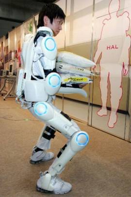
Fig. 8 HAL exoskeleton
Exoskeleton is special robotic suit, that
can be worn on human body and that senses human body movements and supports
human with additional strength and accuracy.
To know torque moments needed to move every
joint in human body during regular gait, together with knowing torque moments
needed to move with construction of exoskeleton, is necessary for choice and
dimensioning of actuators, used for supporting of human movement.
After design of exoskeleton, it can be added
onto human body in Solid Works and new simulation can be created. After this,
actuator parameters can be defined. Using computer simulation is very helpful
for design of robots, because it saves time, material, money, predicts mistakes
and gives very effective tool for construction.
This article is a
part of solution of project VEGA – 1/3229/06.
Resources
[1] Šmíd, M.: Ergonomické parametry,
SNTL – Nakladatelství technické literatury, Praha, 1977
[2] http://biomech.ftvs.cuni.cz/pbpk/kompendium/biomechanika/
/geometrie_hmotnost.php
[3] Novák-Marcinčin, J. – Smrček, J.:
Biorobotika, Elfa s.r.o. Košice, 1998
[4] Cybernics Laboratory at the University of
Tsukuba. The Robotic Suite HAL (Hybrid Assistive Limb).
http://sanlab.kz.tsukuba.ac.jp/HAL/indexE.htmlAvailable
atAccessed April 18, 2005