Технические
науки/6. Электротехника и радиоэлектроника
К.б.н.
Gabaev D.D.
A.V. Zhirmunsky Institute of Marine Biology, Far eastern Branch, Russian
Academy of Sciences, Vladivostok, Russia
The certain covering of conductors
can aid in problems
related
to room-temperature superconductivity
Keywords: coated metallic conductors,
room-temperature superconductivity
ABSTRACT: High – temperature
superconductors are required in many fields of modern technology. However
theirs widespread are prevent of complexity creation of low consistent
temperature for superconductors and work content theirs preparation and
operation. I measured the electrical
resistance of a number of metallic conductors, which I coated with materials of varying compositions and the
are found that when nichrome wires were covered with clean bone glue, there was
a conspicuous decrease in this resistance; with conductors containing iron
covered with clean bone glue, the resistance decreased to zero.
Introduction
Many useful mechanisms
and devices are not created because the problem of room - temperature
superconductivity is not solved. Till now superconductors should be cooled by
liquid nitrogen, that considerably complicates of their use. However my
analysis of the literature has allowed to conclude, that for occurrence of
superconductivity the low temperature is not obligatory. The following pieces
of evidence support the above hypothesis. the
discovery of high-temperature superconductivity in the mid-1980s1,2
overthrew the idea of temperature being a major factor in producing superconductivity.
it became clear that a great deal
depends on the composition of the doping used in such conductors1,2,3. studies
of the internal structure of cuprates and pnictides led researchers to the idea
that a superconductor is a hamburger, in which the electric current flows
through the “meat,” while the “buns” act as a supplier of electrons4.
The meat in those crystal sandwiches is represented by layers of copper oxide
or iron pnictides, composed of alternating layers of atoms. examination under high magnification of
the thin films that cover the crystal substratum revealed that the cuprate
coating consists of spiral ladders with a screw displacement; this structure
produced twisting in the lines of the magnetic field and facilitated high-temperature
superconductivity5. In the Cuo2 layers,
all the atoms were at almost the same level. However, in the FeAs layers, the arsenic atoms were situated above or below the iron
atoms, and four arsenic atoms, surrounding each iron atom, were located at the
tops of a tetrahedron6,7. The crystal lattices of recently
synthesized superconductors also have a tetragonal structure8,9,10.
Approaching the critical temperature for creation the tetragonal structure
appears to be an important factor in the superconductivity of pnictides6,7,8.
It appears likely that the pyramidal structure protects the conductor from the
noise produced by electromagnetic and sound waves, which cause oscillations in
the positive ions and thereby hinder the flow of electrons. It has long been known
that placing conductors within a pyramid increases the temperature at which
superconductivity appears11. a
number of studies have investigated the changes in the long-range
stripe-similar sequence at the critical temperature, which promotes the occurrence
of high-temperature superconductivity12. quasiparticle interference, in which particle-like behavior
disappears as a result of defects in a material, creates standing waves and
promotes superconductivity13. Based on the above observations, I conclude
that when a conductor is isolated from electromagnetic and sound waves, the
positive ions in the conductor’s crystal lattice go into a dormant state and do
not impede the flow of electrons. And I began to test various materials as a
covering for conductors.
Results
It was found that in a 0.2-mm-diameter nichrome wire, which was coiled
into a spiral with a 7-mm diameter and covered with the experimental
composition, the electrical resistance did not decrease at ordinary room
temperature. The electrical resistance likewise showed no reduction when the
wire in the spiral was stretched to twice its original length. this was probably due to the magnetic
field generated by the electric current as it passed through the spiral wire.
It has long been known that magnetic fields destroy superconductivity4.
The experimental coatings decreased the resistance after the wire was wound
into large coils (100.0 mm in diameter) or folded in the form of a zigzag. With
the iron wire, the resistance decreased to zero (Fig.1).
The initial resistance of the water heater with the stainless
steel sheath was 6.3 ohms; after the sheath was coated with a 0.5-mm-thick
layer of bone glue, resistance in the sheath decreased to zero at room
temperature. The bone glue is an insulator. electrical
resistance in a 1.5-mm-diameter iron wire after the bone glue as well decreased
to zero at room temperature (fig.
2).
Thinning the layer of bone glue to a thickness of 0.05 mm caused the
resistance in the sheath to increase to 4.5 ohms. However, after the heater was
covered with Moment rubber glue and then allowed to dry, the resistance once
again decreased to zero. Placing ordinary magnets on the heater did not affect
its the electrical resistance. Five
days after the conducting the resistance measurements, I repeated the tests,
and the results I obtained were close to the initial ones.
There was a statistically
significant difference between the initial electrical resistance in the nichrome
wires and the resistance after coating: t (40)= 3.409; df = 39; p = 0.0015.
When the nichrome wire was covered with bone glue, the difference between the
initial electrical resistance in the nichrome wires and the resistance after
coating was as follows: t (11) = 2.32; df
= 10; p = 0.043. When the nichrome wire was covered with Moment rubber glue, the difference
between the initial electrical resistance in the nichrome wires and the
resistance after coating was as follows: t
(10) = 2.88; df = 9; p = 0.018. Non-metric multidimensional scaling
analysis showed that the coating of bone glue and mixture of bone glue with Ca
(H2PO4)2 + CaCO3 produced the
greatest decrease in resistance in the nichrome wire (Fig. 3).
Under a scanning electron microscope, it
was evident that the various coatings showed defects in their structure; these
defects were 0.5–40.0 µm in size (Fig. 4). the
coating that provided the greatest decrease in resistance in the nichrome wire
(bone glue) had defects that measured about 1.0 µm.
discussion
High–temperature
superconductors are used in many fields of modern technology. However, several
obstacles prevent the widespread use of such superconductors. The first of
these is the complex issue of creating constant low temperatures that allow the
superconductors to function properly4. It has been reported that
superconductors containing iron (pnictides) require lower temperatures than
cuprates6.
There is an ongoing search
for new materials that can function as superconductors2,3; however, solving the problem of room-temperature
superconductivity has reached an impasse. practically
all existing inorganic substances have been subjected to trials as part of this
search, but no superconductivity at room temperature has been found14.
previous research efforts have
examined the phenomenon of superconductivity particularly with regard to the
doping used in the conductors1,2, and it has emerged that such a
doping should certainly not be metallic6,9. However, no tests have
been conducted on a coating similar to bone tissue.
I
covered metallic conductors with several kinds of coatings that had essentially
a similar composition to that of the cranial bones. My results showed that when
nichrome wires were coated, there was a significant reduction in the electrical
resistance. the greatest
reduction in resistance was observed when the wires were covered by clean bone
glue. When this coating was used on iron conductors, the electrical resistance
was reduced to zero.
Conclusion
In the present study, I have
demonstrated that when coated with bone glue, metallic conductors exhibit
considerably decreased electrical resistance at room temperature; when the
conductor contained iron, the resistance fell to zero. covering conductors with a thin layer of bone glue plus Moment
rubber glue imparted elasticity, resistance to impact, and stability to
moisture and magnetic fields without loss of superconductivity. the results of this study demonstrate
that it is possible to create a covering for conductors that decreases electrical
resistance to zero.
methods
To determine the possible influence
of a covering on the conductivity of metals, I covered metal conductors with
bone glue, which has been used by carpenters over the past century for gluing
wood. Bone is a calcified connective tissue, composed of cells within a solid
basic substance. Approximately 30% of this basic substance consists of organic
compounds, mostly in the form of collagen fibers, and the remaining 70% is
inorganic. The major inorganic component of bone is hydroxyapatite—Ca10
(PO4)6 (OH)2, but bone also contains various
amounts of sodium, magnesium, potassium, chlorine, fluorine, carbonates, and
citrates15. To determine the optimum coatings for the conductors, I
tested several compounds, including pure bone glue.
Instruments. For the
conductors, I used mostly nichrome and iron wires and also a foreign-made
immersion water heater with a stainless steel sheath (Weltor, Inc.). To measure
the resistance of the conductors, I utilized a household multimeter, DT-831
(ASD-Electro, Inc.) with a range of 200 ohms and resolution of 0.1 ohm. The conductor
coatings: pure bone glue; a dried mixture of superphosphate—Ca(H2PO4)2—and
chalk (CaCO3); a mixture of bone glue and CaCO3 + Ca (H2PO4)2;
a mixture of bone glue and superphosphate—Ca (H2PO4)2
were examined using a scanning electron microscope, EVO-40 (Carl Zeiss, Inc. germany)
Making bone glue
and mixtures. I made the pure bone glue coating using a thermostatic water bath (in
capacity with water capacity with glue and water is placed) by fusing bone glue
granules (bone glue, Usolsk Glue Factory, Russia) in
water at a weight ratio of 1:1 and at a temperature of 65–70°С. The bone glue
mixtures were produced using the thermostatic water bath by mixing the bone
glue with salts or Moment rubber glue (produced of Henkel AG & Co. KGaA, germany).
Coating variants. First, the
resistance of 0.2-mm-diameter nichrome wire was measured. This wire was then
dipped into the following: (1) Moment rubber glue; (2) bone glue, which had
been melted in the thermostatic water bath; (3) humidified superphosphate—Ca (H2PO4)2—which
was mixed with the melted bone glue in the proportion of 50:50; (4) a mixture
in which three-quarters of the volume was CaCO3 + Ca (H2PO4)2
and one-quarter was melted bone glue; (5) a mixture in which three-quarters of
the volume was melted bone glue and one-quarter was Moment rubber glue. The
pieces of wire were immersed in the glue for no longer than one minute.
Resistance was measured in a 1.5-mm-diameter iron wire as well as in the water
heater, in which the diameter of the stainless steel sheath was 4.0 mm. Then,
the pieces of wire were immersed in the melted bone glue. After being removed
from the glue, the conductors were air-dried for six hours, following which
their resistance was measured. After removal from the water bath, the thickness
of bone glue at water heater was 0.5 mm. I then decreased the thickness of the
bone glue layer to 0.05 mm by immersion in the hot water. After drying the
conductor again, I measured the resistance of the sheath, then dipped the
conductor in the Moment rubber glue, dried it, and again measured the
resistance. I then attached several household magnets to the sheath and
measured the resistance.
Statistics. Data were analyzed using the
Statistica statistical package
(6.0 Version). The results were expressed as means and with a 95% confidence
interval. The Kolmogorov-Smirnov test was employed to analyze the normal
distribution of the variables (p <
0.05). The data followed a normal distribution and were therefore analyzed
using parametric tests. Student’s t test
for dependent samples was utilized to assess the differences in the resistance
of electric current in the nichrome wires before and after the coverings were
applied. For graphical representation of the data, non-metric multidimensional
scaling ordination was carried out using the Bray-Curtis distance. before calculation, the data were
transformed according to the method adopted by16. For each variant, I coated 5–11
nichrome wires. In all, 40 wires were employed.
REFERENCES
1. Gerber, C., Anselmetti,
D., Bednorz, J.G., Mannhart, J., and Schlom, D.G.,
1991. "Screw dislocations in high –Tc films", Nature, vol. 350, pp. 279-280.
2. Hawley, M., Raistrick, I.D.,
Beery, J.G., Houlton, R.J., 1991. "Growth
mechanism of sputtered films of Yba2Cu3O7
studied by scanning tunneling
microscopy",
Science, vol. 251, pp. 49-51.
3. Amato, I., 1991. “Spiral forest” may hold clue to thin-film superconductivity",
Science, vol. 251, pp. 1564-1565.
4. Collins, G., 2009. "Clue from iron". V mire nauky, vol. 10, 60-67.
5. Garwin,
L., 1991. "Whorls upon whorls".
Nature, vol. 350, 277.
6. Kamihara, Y., watanabe, T., Hirano, M., and Hosono H.,
2008. "Iron-based
layered superconductor La[O1-xFx]FeAs
(x=0.05-0.12) with T0 = 26K", Journal
American
Chemical Society, vol. 130, pp. 3296-3297.
7. Matsuishi, S., Inone., Nomura T., Yanagi H., Hirano
M., and Hosono H., 2008 .
"Superconductivity induced by co-doping in quaternary
fluoroarsenide
CaFeAsF." Journal American Chemical
Society. vol. 130, pp. 14428-14429.
8. Imamura, N.,
Mizoguchi, H., and Hosono H., 2012. "Superconductivity in
LaTmBN
and La3Tm2B2N3
(Tm = transition metal)
synthesized under high
pressure".
Journal American Chemical Society. vol. 134, pp. 2516-2519.
9. Scheidt.
E-W., Hathwar, V.R., Schmitz, D., Dunbar, A. et al., 2012.
"Superconductivity
at Tc = 44 K in LixFe2Se2(NH3)y".
Europe of Physics Journal
B. vol. 85, pp. 279–283.
10. Engelmann, J., Müller, K.H, Nenkov, K., Schultz,
L., et al., 2012.
"Metamagnetic effects in epitaxial BaFe1.8Cr0.2As2 thin films".
Europe of
Physics Journal B. vol. 85, pp. 406-409.
11. Gatsunaev, N., 1999. "Rectification of
space". Be sound. vol. 9, pp. 96-99.
12.
Daou, R., Chang, J., LeBoeuf, D. Cyr-Choiniére, O. et al., 2010. "Broken
rotational symmetry in the pseudogap
phase of a high-Tc
superconductor".
Nature. vol. 463, pp. 519-522.
13. Moler, K.A., 2010. "How the cuprates hid their
stripes". Nature. vol. 468, 643
-644.
14. Comarov, S.M., 2012. "Superconductor".
Chemistry and life. vol. 4, pp. 26-29.
15.
Taylor, D.J., Green, N.P.O., Stout, G.W., 2010. "Biological Science"
1&2
(Ed. R.Soper). Moskow
16. Clarke, K.R. & Green, R.H., 1988. "Statistical design and
analisis for a
“biological
effects” study. Marine Ecology Progress Series. vol. 46, pp. 1-3.
Figure 1. Variations in the electrical resistance
(ohms, 20°C) of conductors with various coatings. The control instrument
reading in the experiments was with the absence of a conductor. (A) Resistance
in the 4.0-mm-diameter sheath of the water heater before (black) and after
(white) coating with bone glue; (B) resistance in a 1.5-mm-diameter iron wire
before (black) and after (white) coating with bone glue; (c) resistance in a 0.2-mm- diameter
nichrome wire before (black) and after (white) coating with bone glue; (d) resistance in a 0.2-mm- diameter
nichrome wire before (black) and after (white) coating with Moment rubber glue;
(e) resistance in a
0.2-mm-diameter nichrome wire before (black) and after (white) coating with a
mixture of bone glue and Moment rubber glue; (f)
resistance in a 0.2-mm-diameter nichrome wire before (black) and after (white)
coating with a mixture of salts—Ca (H2PO4)2 +
CaCO3—and bone glue; (g)
resistance in a 0.2-mm-diameter nichrome wire before (black) and after (white)
coating with a mixture of superphosphate—Ca(H2PO4)2—and
bone glue.
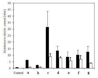
Figure 2. Measuring electrical resistance (ohms, 20°C)
in a conductor containing iron. (a) The control instrument reading in the
experiments was with the absence of a conductor; (b) electrical resistance in
the sheath of the water heater before the covering was applied; (c) electrical
resistance in the sheath of the water heater after the bone glue was applied;
(d) electrical resistance of the covering; (e) electrical resistance in a
1.5-mm-diameter iron wire before the covering was applied; (f) electrical
resistance in a 1.5-mm-diameter iron wire after the bone glue was applied.
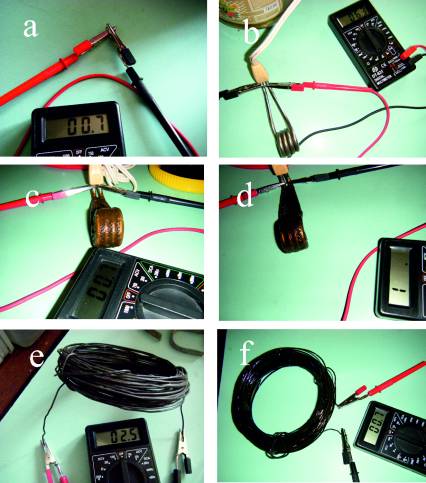
Figure 3. Non-metric multidimensional scaling
ordination analyses of electrical resistance in the nichrome wires before and
after the different coatings were applied. Bonbef = befor covering of
bone glue, bonaft = after covering of bone glue, mombef = befor covering of Moment
rubber glue, momaft = after covering of Moment rubber glue, sulbef = befor
covering of a mixture of salts and bone glue, sulaft = after covering of a
mixture of salts and bone glue.
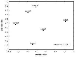
Figure 4. View of the coatings at high magnification. (a) The pure bone
glue had cavities owing to microbubbles of air; (b) dried salts—Ca (H2PO4)2
+ CaCO3—obtained by mixing with water under carbon dioxide aeration
show no structural disturbances; (c) the mixture of bone glue and salts—Ca (H2PO4)2
+ CaCO3—displays disturbances in its structure; (d) the mixture of
bone glue and superphosphate—Ca (H2PO4)2—had
disturbances in its structure.
