Технические науки/2.Механика.
A.A. Suvorov
Scientific adviser: Ph.D., A.N. Mumortsev
Samara State University of Architecture and Civil
Engineering,
The Russian Federation.
Using
a computerized environment «Mathcad 15" to generate functions of internal
forces in the case of simple bending single-span beam.
In solving real-world problems associated with static and
dynamic calculation of building structures, are using the well-known software
packages. The implementation of algorithms for solving these problems in
computational processors can solve highly complex problems and produce more
accurate results.
In the
establishment of separate blocks of tasks on the basis of «Mathcad», related by
the calculation of single-span beams to the action of static load, there are difficulties
in obtaining the distribution curves, movements in various forms of stress.
Various combinations of loads cause four types of internal forces in the
section of a beam. These efforts include: bending moment "M", the
shear force «Q». The longitudinal strength of «N», and torque «Mk»,
hypothetically, in the sections do not occur.
It is especially difficult for manual calculation defines
the displacement (deflection, angles of rotation, etc.) using the method of
initial parameters, integrals of Mohr, require direct numerical integration
over (Vereshchagin rule or Simpson's formula), or where the complexity of
integrating it manually. In an environment of computer algebra «Mathcad»
integrating data diagrams reduced to a few simple steps, and the result is
here! But there is a complexity in the construction of diagrams that you want
to multiply, or integrated.
This article contains the function blocks, which are based
on diagrams of internal forces, while using linear or parabolic functions and
Boolean operators. They are easy to integrate, allow you to build diagrams of
effort for all values of the coordinates and the application of
static load, and to solve the problems of structural mechanics in the
environment «Mathcad» in the future.
I. Bending moment and shear forces.
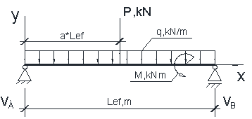
Figure
1. Design model of the single-span beam loaded in three variants static load.
1. Diagrams
of bending moment and shear force of the concentrated load
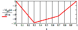
- The
function of the bending moment and the corresponding diagram:
![]()
|
|
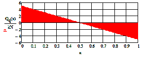
- The
function of the shear force and the corresponding diagram:
![]()
|
|
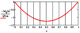
2. Diagrams
of bending moment and shear force of a uniformly distributed load
- The
function of the bending moment and the corresponding diagram:
![]()
-
Functions of the shear force and the corresponding diagram:
![]() or
or ![]() .
.
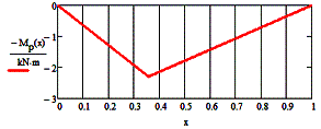
3. Diagrams
of bending moment and shear force of the two concentrated loads
Block of functions.
-
Support
reactions:
![]() ,
,![]()
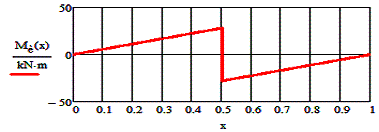
-
The function of
the bending moment diagram and the corresponding MP2:
![]() - Auxiliary factor
- Auxiliary factor![]()
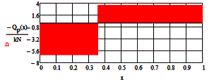
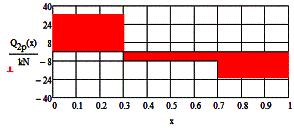
-
The function of
the shear force Qr2 and the corresponding diagram:
![]()
|
|
4. Diagrams
of bending moment and shear force from the external bending moment
-
The reference
response from the bending moment:
![]() ,
,![]()
-
The function of
the bending moment and the corresponding diagram:
![]() ;
;
|
|
-
The function of
the shear force and the corresponding diagram:
![]()
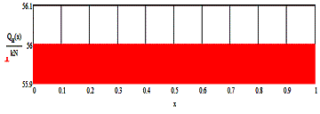
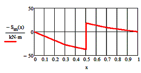
5. Diagrams
of internal forces from the combination of all loads
These diagrams are constructed using the previous
diagram by adding them up.
Diagrams of bending moment (Sm)
and shear force (SQ) from the action of concentrated, distributed,
moment loads according to claim 2, item 4.
-
The function of
the bending moment and the corresponding diagram:
![]()
|
|
-
The function of
the shear force and the corresponding diagram:
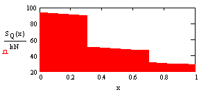
![]()
The diagrams can
be obtained by summing for an unlimited number of applied loads. The total diagram
also can be summed up with the other curves and a slipstream.
Note: a,
a1, a2, a3 - the coordinates of the application loads, ![]() ; Lef - the estimated
length of the beam; P - concentrated load; q - uniformly distributed load. For
the construction of the diagrams from a single effort to take P = 1. VA,
VB - support reactions. Graphic diagrams are constructed by a
negative value of effort ("on the stretched fibers")
; Lef - the estimated
length of the beam; P - concentrated load; q - uniformly distributed load. For
the construction of the diagrams from a single effort to take P = 1. VA,
VB - support reactions. Graphic diagrams are constructed by a
negative value of effort ("on the stretched fibers")
References:
1.
A.V.
Alexandrov, V. Potapov, B.P. Derzhavin / / Strength of Materials. Textbook for high schools. - 4th
ed., Rev. - M.: Higher School, 2004. - 560 s.: Ill.
2. E. Makarov / / Engineering
calculations in MathCad 15. Training course. St. Petersburg.: Peter, 2011. -
400 s.: Ill.