Cand. tech. sci Kostinsky S.S.
Platov South-Russian State
Polytechnic University (Novocherkassky polytechnic institute), the Russian Federation
Loss
evaluation of the active electric power in tank and air transformers at the
uniform and non-uniform load pattern
The
electrical energy lost in the transformer in the course of transformation alternating-current,
is oozed in the form of heat in windings, magnetic system and other parts of
the transformer. In tank transformers magnetic system and windings are washed
by the circuit-breaker oil, which level considerably above level of magnetic
system. The particles of oil adjoining to hot surfaces, heating up, direct
upwards and donate heat in a environment through walls and a cap of a tank. Between
windings both magnetic system, on the one hand, and oil - with another, the
certain temperature difference is erected. However the temperature of oil and
other parts of the transformer in different zones on height are various.
In
view of complexity of thermal processes in the transformer at their theoretical
analysis it is necessary to do a series of simplifications. With that end in
view windings and the magnetic system, representing a combination of various
materials, exchange the homogeneous skew fields. Such simplification is
admissible provided that the substituting homogeneous skew field at the same
external sizes and the same amount of oozed heat possesses the equivalent heat
capacity. Besides, for each device thermal chains (the magnetic system, a
winding, oil, a tank) introduce some its medial temperature.
According to [1] oozed in a skew field for the elemental time interval dt
thermal energy П · dt partially is spent for skew field rise in temperature on dυ
and partially tapped in environmental space. At any moment the balance of
thermal energy expressed by a differential equation takes place
П · dt = С · dυ + K · υ · dt,
where С – the full
heat capacity of a skew field;
K – amount of heat tapped by a heat-absorbent surface in unit
of time at a difference between temperature of a surface and temperature of medium
in 1°С;
υ – temperature difference between the given skew field and a
surrounding medium.
The
heating of the transformer concerning oil at the erected thermal conditions can
be accepted to proportional losses in the transformer.
Deficiency
of the definition of losses of the active electrical energy featured above an
expedient of the transformer is that for account meanings of the physical
quantities depending on design data of the transformer are required, not being
nameplate data and complicated for definition in practice with a split-hair
accuracy.
Counters
of losses of the active electric power are applied to definition of losses for
example [2] which principle of operation is grounded on Joule law. Deficiency
of such counters is that they spot energy of losses in transformer windings,
but losses also include losses in magnetic system, a tank, and as losses from
asymmetry and a nonsinusoidal current. For the account of losses also it is
necessary to know resistance of object on which measuring which varies
depending on heating and surrounding medium temperature are made. Told all
above leads to a drop of a measurement accuracy of losses of electrical energy.
On
the basis of law of conservation energy it is possible to note heat-balance
equation in other form:
![]() (1)
(1)
where ΔP – active power losses in the
transformer for dt;
с – specific heat capacity;
G – transformer
weight;
dΘ – increase of
temperature of the transformer;
α – coefficient
of a heat dissipation from a surface;
S – surface
area;
ΔΘ – difference
between temperature of the transformer and an environment temperature.
The
transformer heating time constant is spotted according to [1]:
![]() . (2)
. (2)
At
reaching of the erected temperature the first addend in the formula (1) becomes
equal to zero, and losses become equal to losses in the nominal condition and
develop of idling and short circuit losses.
According
to the formula (2) at the erected temperature of the transformer taking into
account that in the nominal mode of operation of the transformer ΔР = Рind + Рs.c., the equation (1) will become:
![]() ,
,
whence
 , (3)
, (3)
where Рind – idling losses;
Рs.c. – short circuit losses;
Θ∞n – the
erected temperature of the transformer in the nominal condition.
Using
the equations (2) and (3) it is discovered α · S:
 . (4)
. (4)
Considering,
that G, c, S and α are constants
for the concrete transformer and, using formulas (3) and (4), the law of
conservation energy (1) will become:
 . (5)
. (5)
Composed
formulas (5) have the following physical sense:
- ![]() – stored heat
amount in the transformer;
– stored heat
amount in the transformer;
-  – amount of heat
donated in a surrounding medium.
– amount of heat
donated in a surrounding medium.
Losses
of active electrical energy in magnetic system and transformer windings are
oozed in the form of heat. As it was specified in the beginning of paper in
view of complexity of thermal processes in the transformer at their theoretical
analysis it is necessary a winding and the magnetic system, representing a
combination of various materials, to exchange the homogeneous skew fields. The
specified assumption leads to increase of an error of evaluation of heat oozed
with devices of a construction of the transformer since the magnetic system at
a normal mode of operation heats up essentially less, than a winding drawings 1
and 2. Installation sites of the temperature sensing devices which effects of
measuring are shown in drawings 1, 2, are given in drawing 3.
|
|
|
|
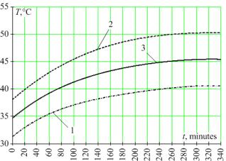
Fig. 1. The graph of a modification of temperature of a winding
from time: 1, 2 – the approximated data gained from
temperature sensing devices 5 and 6 (fig. 3) accordingly; 3 – medial
meaning of temperature |
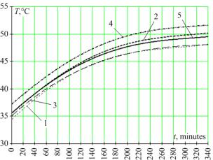
Fig. 2. The graph of a modification of temperature of magnetic
system from time: 1 – 4 – the approximated data gained
from temperature sensing devices 1 – 4 (fig. 3);
5 – medial meaning of temperature |
For
the purpose of reduction of an error of account of losses of the active electric
power for the air transformer it is necessary to part the losses oozed in
magnetic system and a winding and then expression (5) will become:
 , (6)
, (6)
where Тind – heating time constant
of magnetic system;
ΔΘind – difference
between temperature of magnetic system and a surrounding medium;
dΘind – gain of temperature of
magnetic system for space of time dt;
Тs.c. – heating time constant of winding;
ΔΘs.c. – difference between temperature of winding and a surrounding
medium;
dΘs.c. – gain of
temperature of a winding for space of time dt;
Θ∞n ind – the erected
temperature of magnetic system in the nominal condition;
Θ∞n s.c. – the erected
temperature of a winding in the nominal condition.
|
|
|
Fig. 3. Installation sites of temperature sensing devices on the
single-phase air transformer: 1 – 4 – temperature sensing
devices anchored on magnetic system of the transformer;
5, 6 – temperature sensing devices anchored on a transformer
winding; 7 – a temperature sensing device for environment temperature
measuring; 8 – magnetic system; 9 – a winding;
10 – transformer bases |
Composed
formulas (6) have the same physical sense, as composed formulas (5).
For
the purpose of checkout of working capacity of expression (6) experiment on the
single-phase air transformer with use of the measuring probing devices which have transited metrological checking
has been made. Transformer temperature sensing devices have been anchored on
magnetic system and a winding, the data unit for measuring of an environment
temperature near to the transformer also has been provided. Installation sites of temperature sensing devices corresponded to places
shown on drawing 3.
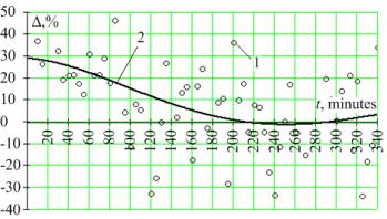
Fig. 4. The graph of an error of evaluation of losses of the active
electric power in the transformer from time: 1 – the calculated
meanings; 2 - approximation of the calculated meanings by a multinomial
of 4-th order
The
graph of an error of evaluation of losses of the active electric power in the
transformer under the formula (6) in comparison with the real (measured) losses
is given in drawing 4. Medial meaning of quantity of an error of evaluation of
losses of the active electric power in the transformer during measuring has
made 9,2 %.
The formula (6) is valid, as it was specified above, for the nominal condition
of the transformer as idling and short circuit losses are accepted by the
invariable. Actually at real loadings the transformer fill varies, owing to what
quantity of losses varies. In this connection at
definition of losses of the electric power it is necessary to discover a power
loss in the transformer on each i-th time interval dt. The
solution of a differential equation (1) for such intervals looks like:
 , (7)
, (7)
where Θi – temperature of a separate device of the transformer;
Θi+1 – temperature of a separate device of the transformer in the
end of an interval dt.
From
expression (7) it is possible to define Θ∞:
 , (8)
, (8)
simultaneously
![]() . (9)
. (9)
From
the formula (9) quantity can be in advance discovered
 , (10)
for each device of the transformer
on observational or design values of losses ΔРn and the erected
temperature Θ∞n. Quantity
α · S is invariable for each device of a construction of
the transformer.
On
the basis of expression (9) taking into account (8) and (10) it is possible to
calculate power losses for each device of a construction in time dt:
 .
.
Active
power net losses in the transformer in time dt develop of losses in each
n-th device of the transformer:
 .
.
Losses
of electrical energy in time dt:
![]() .
.
Summation
of losses for each space of time gives common losses in the transformer for required
space of time at any load pattern.
Deductions.
1. The essence of an offered expedient of definition of losses of
the active electric power consists in a tank transformer that the transformer and surrounding medium temperature and in measuring
space of times equal on two, three orders less than a thermal time constant is
measured, the gain of temperature of the transformer is calculated, the
difference between temperature of the transformer and a surrounding medium is
spotted and losses of the active electric power in the transformer are
calculated under the formula (5).
2. The essence of an offered expedient of definition of losses of
the active electric power consists in the air transformer that the temperature of magnetic system is measured, a winding and a
surrounding medium and in measuring space of times equal on two, three orders
less than a thermal time constant of the transformer, are calculated gains of
temperatures of magnetic system and a winding, differences between temperatures
of magnetic medium, a winding and a surrounding medium are spotted. Losses of
the active electric power in the transformer are calculated under the formula
(6).
3. At
a non-uniform load pattern it is expedient to calculate electric power losses
in each device of a construction of the transformer separately taking into account
the rated erected temperature for each condition of a fill of the transformer
and invariable design data of its devices. Such solution considers losses in
windings, in magnetic system, from current and voltage upper harmonics, from
asymmetry of a loading.
4. The
formula (5 and 6) allow to consider all losses of the active electric power
oozed in the transformer in the form of heat. Medial meaning of quantity of an
error of evaluation under the formula (6) during experiment has made 9,3 %.
The
literature:
1. Petrov G.N. Electric machine. In 3 parts. Part 1. Introduction. Transformers. The textbook for
high schools. М.: Energy, 1974. 240 pages.
2. The patent.
2380715 Russian Federations, МPК G 01 R 19/02, G 01 R
11/00. The counter of losses of the electric power / V.F. Ermakov,
E.S. Balykin, E.V. Ermakova, I.V. Zajtseva, J.M. Reshetnikov;
V.F. Ermakov. № 2008128966/28; announcement 15.07.2008;
it is published 27.01.2010.