B.Sazambayeva, G. Kuanyshev, M.Zhumanov, S. Kozhataev
Kasakh National Research Technical University Behalf
K.Satpayev,Almaty,22 Satpayev street
DETERMINATION
OF TORQUES ON THE TUBULAR BELT CONVEYOR
1.
Method calculating
of tubular belt conveyor
In operation, when
the design parameters of a tubular belt conveyor reach a certain value
(critical value), begins intensive growth of oscillation amplitudes. In this
case, the operation of the conveyor is not possible due to intense vibration.
Vibration breakages in the loss of stability is usually accompanied by costly
repairs, significant unplanned downtime and sometimes devastating consequences.
Used in work approach makes it relatively easy to analyze the vibration
resistance of pipelines and assess their critical parameters. Knowledge
of these parameters allows you to design quickly and produce
tubular belt conveyors with low vibration and high
operational reliability.
2. Perturbed motion of a
tubular belt conveyor Introduction
Consider the straight portion of the tubular
belt conveyor (Figure 1)
[1,2,3,4,5]
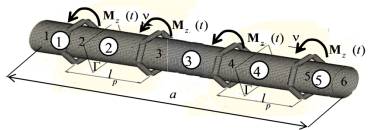
Fig. 1.
Finite element model of the linear
portion of the tubular conveyor
belt.
Consider the straight
portion of the tubular belt
conveyor as a set of five finite elements with
six nodes (Figure 1). Formation of the global matrix of inertia, stiffness, damping and vector nodal loads described
in [1,2]. Let us write the equation
of forced torsional oscillations of a straight section of the conveyor belt tube (Figure 1)
in the form of [6,7,8,9,10]:
 (1)
(1)
with the initial conditions
![]() (2)
(2)
Here ![]() ,
,![]() ,
,![]() respectively global
matrix of inertia, damping and stiffness,
respectively global
matrix of inertia, damping and stiffness, ![]() global vector of external
forces. The matrices of inertia, stiffness and the nodal displacements vector of finite element model of the tubular belt conveyor have the
form [1,2]:
global vector of external
forces. The matrices of inertia, stiffness and the nodal displacements vector of finite element model of the tubular belt conveyor have the
form [1,2]:
In practical
calculations damping matrix for each ![]() finite element is represented as a linear
combination
finite element is represented as a linear
combination
![]() (3)
(3)
Where ![]() – proportionality
coefficients. For example,
when
– proportionality
coefficients. For example,
when ![]() damping matrix is
proportional to the matrix of
inertia ("external" friction),
when
damping matrix is
proportional to the matrix of
inertia ("external" friction),
when ![]() damping matrix is
proportional to the stiffness matrix ("internal" friction).
damping matrix is
proportional to the stiffness matrix ("internal" friction).
To determine the equivalent
nodal torsional moments ![]() , arising
from the interaction of the tape of the tubular conveyor with support idlers, consider
the tape movement inside the idlers.
Idlers are the
six rollers [8,14,15],,
, arising
from the interaction of the tape of the tubular conveyor with support idlers, consider
the tape movement inside the idlers.
Idlers are the
six rollers [8,14,15],,
forming a ring. Thus, the three upper and three
lower rollers rotating in opposite directions Fig.2.
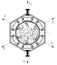
Fig. 2.
The forces acting on the tape in idler
Due
[5,7,8,11,13]
![]()
Where ![]() pressure force on the i-th roller,
pressure force on the i-th roller, ![]() torsional shear angle. The rotating moment at the point of contact
of tape and i-th roller is calculated as:
torsional shear angle. The rotating moment at the point of contact
of tape and i-th roller is calculated as:
![]() (4)
(4)
Thus, the total torque with
(4) is equal to
![]()
Then the vector of
nodal loads to the m-th finite element, taking into
account (4) has view [2,3]
 (5)
(5)
Consequently, the vector of
equivalent nodal loads ![]() of
concentrated torques in idlers will be equal to:
of
concentrated torques in idlers will be equal to:
Thus, the equation of
perturbed motion of torsional oscillations of the straight section of the belt tube conveyor
(Figure 1) has the form
 (6)
(6)
It is
assumed that the damping matrix is
proportional to the matrix of
inertia. Thus, the coefficient of
proportionality ![]() .
.
Since oscillation
stability is determined by reacting the
first lower waveforms
in equation (6) as
a first approximation may be
considered not all waveforms
![]() but only
but only ![]() .
.
In this case, the
solution of equation (6) in the form
![]() ,
(7)
,
(7)
Where ![]()
![]() . Здесь
. Здесь ![]() – diagonal
matrix of squares of the natural
frequencies,
– diagonal
matrix of squares of the natural
frequencies, ![]() – identity
matrix of dimension (
– identity
matrix of dimension (![]() ),
),![]() –matrix
of natural modes of dimension (
–matrix
of natural modes of dimension (![]() ).
).
Inserting (7) into (6) and
cancel out the common multiplier ![]() we obtain the equation
we obtain the equation
![]() (8)
(8)
The characteristic equation for
determining the indicator ![]() takes the form
takes the form
![]() (9)
(9)
Here
![]() the matrix with dimension (
the matrix with dimension (![]() ).
).
When you change
parameter ![]() the characteristic
indices
the characteristic
indices ![]() move in the complex plane (Fig.
3). The real roots of the equation (9) corresponds to a monotonous (not oscillating)
movements of the straight section
of the belt tubular conveyor and complex - the
oscillatory motion. Thus particular
solution will be attenuated,
periodical or infinitely increasing
function of time depending on whether
the real part of the root (9) is
negative (Fig. 3a), is zero (Fig. 3b)
or positive (Fig. 3c).
move in the complex plane (Fig.
3). The real roots of the equation (9) corresponds to a monotonous (not oscillating)
movements of the straight section
of the belt tubular conveyor and complex - the
oscillatory motion. Thus particular
solution will be attenuated,
periodical or infinitely increasing
function of time depending on whether
the real part of the root (9) is
negative (Fig. 3a), is zero (Fig. 3b)
or positive (Fig. 3c).
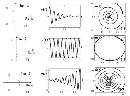
Figure
3.
Location roots of the equation (4) in the complex plane,
typical trajectories and
phase portraits.
In the field of
sustainability ![]() On the
part of the critical surface, which corresponds to the transition to the divergence, one of the characteristic roots of the equation (9) vanishes. On the critical surface, which corresponds to a transition to flutter at least a pair
of roots is a complex conjugate
(Fig. 3).
On the
part of the critical surface, which corresponds to the transition to the divergence, one of the characteristic roots of the equation (9) vanishes. On the critical surface, which corresponds to a transition to flutter at least a pair
of roots is a complex conjugate
(Fig. 3).
2. The solution of test task
To illustrate the practice
of the developed approach, consider the straight
portion of the tubular belt
conveyor (Figure 1) for the following parameters: ![]() the length of the linear portion of the conveyor;
the length of the linear portion of the conveyor; ![]() Нм - the resulting torque in idlers;
Нм - the resulting torque in idlers; ![]() м - the distance between the idlers;
м - the distance between the idlers; ![]() м - the mean radius of the circumference of the pipe;
м - the mean radius of the circumference of the pipe; ![]() м - tape thickness;
м - tape thickness; ![]() Pa - shear modulus;
Pa - shear modulus; ![]() angle
characterizing the degree of filling the cross section of the tape by load;
angle
characterizing the degree of filling the cross section of the tape by load;
![]() the density of coal;
the density of coal; ![]() the density of
tape;
the density of
tape; ![]() reduced density;
reduced density; ![]() the moment of inertia of rotation of the tube;
the moment of inertia of rotation of the tube; ![]() moment of inertia of the load rotation;
moment of inertia of the load rotation; ![]() linear mass moment of inertia;
linear mass moment of inertia; ![]() torsional stiffness section;
torsional stiffness section; ![]() m/s - the conveyor belt
speed.
m/s - the conveyor belt
speed.
Figure 4 shows
the dependence of the first two lower
frequency torsional vibrations,
and the real part of the characteristic
exponent ![]() of the tubular conveyor belt (Figure 1) as a function of the speed of the belt
of the tubular conveyor belt (Figure 1) as a function of the speed of the belt ![]() on the conveyor. The solid
and dashed lines correspond to the
first and second natural frequency of the torsional oscillations, respectively. From
Figure 4 it is seen that with increasing the speed of the conveyor belt lower natural frequencies decrease and when
on the conveyor. The solid
and dashed lines correspond to the
first and second natural frequency of the torsional oscillations, respectively. From
Figure 4 it is seen that with increasing the speed of the conveyor belt lower natural frequencies decrease and when ![]()
![]()
![]() , which corresponds
to the transition to unstable torsional vibrations according to the type of
divergence.
, which corresponds
to the transition to unstable torsional vibrations according to the type of
divergence.
Thus, the critical speed
of the conveyor belt as is equal 
When ![]() torsional oscillations of the straight section of the
belt tubular conveyor are sustainable.
torsional oscillations of the straight section of the
belt tubular conveyor are sustainable.
3.
The main results and conclusions
The proposed approach is based
on the finite element method, makes
it relatively easy to assess
critical parameters of tubular belt conveyors. It is
shown that the critical speed of movement of conveyor belt is equal 
References:
1.Дмитриев
В.Г., Сергеева Н.В. Определение распределенных сопротивлений движению ленты на
прямолинейных участках трассы ленточного трубчатого конвейера // Горный
информационно-аналитический бюллетень. - 2008. - №9. - С. 245 - 249.
2. Sarguzhin M.Kh., Dzhienkulov Z.S.,
Sazambaeva B.T., Imangaliyeva A.E.
Determination of
resistance to movement of the running belt circuit of conveyor syste// Materiály X mezinárodní
vědecko-praktická conference. «Efektivní nástroje
moderních věd – 2014»,
Díl 32. Technické vědy
3. Пертен Ю.А. Крутонаклонные конвейеры. Л:Машиностроение, 1977.-с.215.
4.
Дмитриев В.Г., Ефимов
М.С. Влияние различных факторов на угловые отклонения ленты трубчатого
конвейера. // Горный информационно-аналитический бюллетень. – М.: МГГУ, 2008. -
№8, с. 235 - 237.
5.
B. Sazambaeva , G. Kuanyshev,
Khadeev ,N.T.Zhumanov“On the question of the study of tubular belt conveyors for the
transportation of goods environmentally //Materias of XI International Research
and Praktike Conference SCINCE WITHOUT BORDERS-2015, March-April 7, 2015 / Science
and Education Ltd Sheffied S.60-66
6.
V.Radian, J.Samarin, V. Chirkov “Finite Element Method for dynamic
problems of strength of materials.” - M.: FIZMATLIT, 2013. - 316 p.
7.
Дьяченко А.В. Обоснование метода расчета напряженного состояния
сыпучего груза и нагрузок на опорные элементы при формировании желоба
трубчатого ленточного конвейера. дис. на соискание уч. ст. канд. техн. наук.
Московский государственный горный университет. М. 2006
8.
Сазамбаева Б.Т., Кәдірақын. Г Исследование параметров трубчатого ленточного конвейера
// Вестник КазНТУ №5.- Алматы,
2015С.104-106
9.
Модернизация
Красноярского цементного завода – сайт: www. http://www.sibcem.ru/
10. В.Н.Ивченко,
С.В.Куров, Беспросыпные ленточные конвейеры. Журнал "Горная Промышленность" №4 2005.
11.
В.Г. Дмитриев, Н.В. Сергеева Методика тягового расчета ленточного трубчатого конвейера Журнал "Горная
Промышленность" №4 2011
12.
Шахмейстер Л.Г., Дмитриев В.Г. Теория и расчет ленточных конвейеров. М.:
Машиностроение, 1987. - 336 с.
13.
Сергеева Н.В. Обоснование метода расчета распределенных сил сопротивления
движению ленты на линейной части трубчатого конвейера для горных предприятий. Автореф. дисс. на соиск. уч. степени канд.
техн. наук., Москва, МГГУ, 2000 -24 с.
14.
П.А. Бажанов Методы оптимизации параметров
трубчатого ленточного конвейера Горный информационно-аналитический
бюллетень, 2009, №9,
15.Куанышев
Г.И. Патент KZ № 29011 Трубчатый ленточный конвейер. Республика Казахстан,
Астана, 2014г.