Chernjak M.G., Elina O.V., Gasanov
E.M., Motsnyj M.P.
Oles Honchar Dnipro National
University, Ukraine
Tester of semiconductor elements
The development of radio electronics has set new tasks
for scientists and engineers in the creation of instruments for measuring
electrical voltage, current, frequency, as well as the representation of
waveforms, since a person has no sense organs to evaluate electrical
parameters. Without modern devices, it is impossible to carry out installation
of complex household and professional equipment, its adjustment, and
elimination of faults and errors made during the installation.
A tester is a device that accurately determines the number
of inputs and types of outputs of elements such as field and bipolar
transistors, thyristors, dinistors,
semistors, diode and zener
diode.
The principle of the modern tester of semiconductor
elements is that after connecting the test element to the terminal with the
participation of the control unit there is a mode of testing and indication of
operation: from the microcontroller a set of signals is received, by which the
type, location of the terminals and the basic parameters of the element are
recognized. After that, the data comes to the test result indicator.
The task of this work is to develop a tester of
semiconductor elements with sufficiently wide functional capabilities.
On the basis of the analysis of existing circuitry
solutions [1-4], a tester is selected which, unlike the others, has one LCD
indicator, a compact principle-based circuit based on Atmega
8, and is capable of testing much more types of semiconductor elements. The
circuit improved by replacing the Atmega 8
microcontroller with the Atmega 328 based on the Arduino platform in order to be able for further adding of
new testing algorithms.
Based on the chosen circuit design, a basic circuit
diagram of the device was developed and the experimental breadboard was
manufactured (Fig. 1).
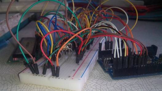
Fig. 1 The experimental breadboard
After successful
checking the circuit on the breadboard, a basic scheme of the tester of
semiconductor elements developed in the software environment Altium Designer - a powerful integrated system of automated
designing of electronic devices. Then a printed circuit board was printed. One
of the main elements of the tester's scheme is Arduino
Uno (Fig. 2).
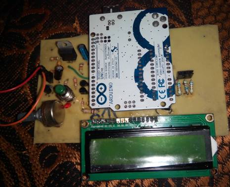
Fig.2 The appearance of the tester before the test
Device testing conducted for different
devices, in particular, for PNP, NPN and field
transistors, various diodes (Fig. 3).
|
|
|
|
|
|
|
|
|
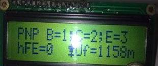

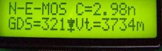
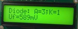
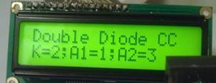
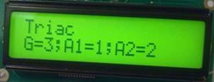
Fig. 3 Test results of the finished device
Thus, the compact and
economical device for testing semiconductor elements has been developed and
tested. The device has wide functionality, which can be improved due to the free
memory of the microcontroller. The tester also has the additional property of
transferring the received characteristics of the semiconductor element to the
computer.
References
1. Voznesenskij A.S., Shkuratnik V.L. Jelektronika i izmeritel'naja tehnika. 2008.
2. Glibina V., Petrov A. Radio. – 2013. – № 12. – P.15-20.
3. Zajcev S.A., Gribanov
D.D., Tolstov A.N. Kontrol'no-izmeritel'nye pribory i instrumenty. 2002.
4. Markus
Frejek AVR-Transistortester,
Embedded Projects Journal, 11. Ausgabe, 2011.