The method of reconstruction of the drive mechanism
for lifting floating crane bucket based on an assessment of durability metal
floating crane.
A.S. Yablokov
Key words: cycle
fatigue experiment, damage, material parameters, the torque converter, impeller,
turbine, reactor wheel, grab
The article discusses the
problem of assessing the durability of metal structures of the engine room of
the floating crane. Examined the effects of the phenomenon of
"suction" grab for floating cranes involved in subsea production. The
solution of the problem - including in the drive mechanism for lifting the
torque converter, as well as the requirements to specifications and design for
such a converter.
Contacts: alex-vodnik@mail.ru
Introduction.
When subsea floating cranes as a
lifting body uses grapple. Hoist and scoop grab the floating crane is not
different from the hoist gantry crane, which when overloaded bulk materials as
well as the lifting body uses grapple. However, when operating in the
water-saturated material of the grapple under water when scooping and lifting
raises additional hydrostatic forces "suction" filtering hydrostatics
and viscous flow of the material in the grapple, which depend on the speed of separation
and scooping material grapple, which leads to stresses in the hoisting ropes
and metal crane. This effect, which occurs in a short period of time, may
exceed the 50% allowable load on the crane and a "peak" [1].
Currently 90% of floating cranes have a lifespan of 15 years or more, which makes their use problematic in underwater mining, as their metal worn and are not designed for such loads.
1. Evaluation of the durability of metal floating crane CPL 5-30.
To assess the durability
of metal floating crane CPL 5-30, was calculated metal frame floating crane
engine room CPL 5-30, Head. №2040, made in 1974 by the "ship" Bor. To
date, the floating crane was committed 902,467 cycles and handled 2,256,168
tonnes (according to the organization of the operator). Material metal crane
St3kp. Determination of stress-strain state of a floating crane performed
depending on the operating conditions of the crane:
1. For the first case,
the calculation was chosen nominal mode of operation of the crane, the
corresponding maximum permissible load capacity - 5 tons, the marginal wind
load working condition - wind speed of 15 m / s, the maximum inertia load and a
maximum roll pontoon - 30.
2. For the second case
selected peak operation of the crane, this mode occurs when using the grapple
in water-saturated material under water, when scooping and lifting raises
additional hydrostatic forces, "suction", filtration, hydrostatic and
viscous flow of the material, depending on the speed scoop up material and
separation of the grapple, which leads to stress the rope hoist and crane
metal. This effect occurs in a short period of time and may exceed 30%
allowable load on the crane and a "peak".
Lifting speed of cargo:
m / s, the maximum weight of the load lifted kN. For a general idea of the
nature of deformation of the frame and identify the location of the nodes that
are critical in terms of durability, the first stage was carried out by elastic analysis account code [2].
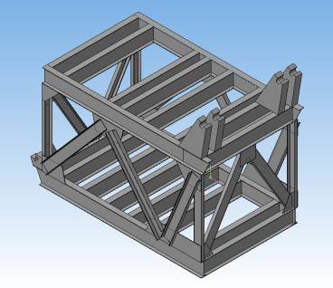
Fig. 1. -
The model of the engine room carcass floating crane.
Physical and mechanical characteristics
of St3 were adopted as follows: Young's modulus of elasticity ![]() mPa, Poisson's ratio ν=0,28, yield point σТ = 230 mPa, density ρ=7820 kg/m3. The frame
was modeled in full size in compliance with specified characteristics and
geometry. Each compound was replaced by a rigid - welded. Modeling supports the
frame also been conducted, but in places bearing frame on the turntable imposed
boundary conditions precluding movement of nodes in all directions and turn
them into these nodes. Based assortments used profiles idealization carcass
structure into finite elements was carried out using 8, 10, 20 - the final
nodal elements are symmetric in cross section.
mPa, Poisson's ratio ν=0,28, yield point σТ = 230 mPa, density ρ=7820 kg/m3. The frame
was modeled in full size in compliance with specified characteristics and
geometry. Each compound was replaced by a rigid - welded. Modeling supports the
frame also been conducted, but in places bearing frame on the turntable imposed
boundary conditions precluding movement of nodes in all directions and turn
them into these nodes. Based assortments used profiles idealization carcass
structure into finite elements was carried out using 8, 10, 20 - the final
nodal elements are symmetric in cross section.
The calculation results
are shown in Table 1, which shows the maximum values of the stresses and
strains in the elements of metal carcass floating crane CPL 5-30.
Table 1 - Results of calculation.
|
№ |
Stress |
mPa |
Strans |
m |
|
1 |
Σ |
149 |
e |
0.964x10⁻³ |
|
2 |
σX |
32,5 |
eX |
0.8x10⁻³ |
|
3 |
σY |
52,6 |
eY |
0.426x10⁻⁴ |
|
4 |
σZ |
65,0 |
eZ |
0.484x10⁻³ |
|
5 |
σXY |
36,6 |
eXY |
0.227 x10⁻³ |
|
6 |
σYZ |
46,7 |
eYZ |
0.29 x10⁻³ |
|
7 |
σXZ |
18,0 |
eXZ |
0.112 x10⁻³ |
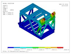
Results of calculation of the
maximum deformations and stresses in the critical elements of the framework
presented in Figure 2. It is seen that the stress state is triaxial
(volumetric) character.
|
|
|
|
a) the equivalent stresses |
b) the total deformation |
|
Fig. 2 - The results of the calculation. |
|
From the analysis of
solutions of the problem (see Table 1) shows that the stress level does not
exceed the yield strength. Figure 3 shows the curve of damage ![]() relative to the number of
loading cycles
relative to the number of
loading cycles ![]() , where Nf – number of cycles to
macrocrack formation. Analyzing the results of the maximum strain and stress
can be concluded that the amount of accumulated damage is in the danger zone
(close to the "critical" value (
, where Nf – number of cycles to
macrocrack formation. Analyzing the results of the maximum strain and stress
can be concluded that the amount of accumulated damage is in the danger zone
(close to the "critical" value (![]() ).
).
The
evaluation of durability of the floating crane CPL 5-30 Head. №2040 concluded
that the development of the resource metal frame of the engine room (residual
life is within the error calculation) and is necessary to overhaul with
replacement metal bearing loaded elements, or the reconstruction of the crane.
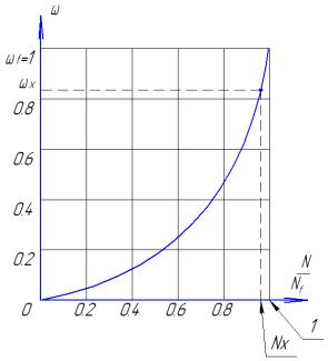
Fig. - 3 - Curve
damage.
2. A method for increasing the
reliability of steel structures and the drive mechanism for lifting floating
crane clamshell.
The
torque converter allows you to automatically adjust the speed of lifting and
closing the grab by creating a feedback between the load on the ropes and speed
scooping and lifting the grab. They allow you to smoothly change the gear ratio
from the motor to the gearbox by 3.5 times in the direction of increasing and
correspondingly increasing the torque on the shaft of the gearbox, which will
overcome the effect of "peak" loads. Additionally, a means, which
prevents the actuator from any overload, since the torque transmission therein
through the liquid, rather than through a rigid kinematic linkage.
Analysis of the properties and characteristics of the
existing torque converters [3, 4] allows us to formulate requirements for them
to be installed in the mechanism of lifting floating crane:
1.Torque converter possessing high speed, must have the appropriate
damping properties to avoid the effect of his work on the high-frequency
oscillations in the hoisting ropes.
2. Torque
converter must ensure operation of the motor drive in optimal conditions, will
not enter when all the input power is spent on "myatie" fluid. Such
requirements are met completely "opaque" torque converters [3, 5, 6],
but the creation of torque converters of this type is problematic [6, 8], so it
is advisable to apply torque converters with a low degree of "transparency"
in the range of 1.0 ... 1.1 in the main working area.
Transparency
- property impeller change the amount of torque when changing the gear ratio
torque converter. If the change gear ratio of torque on the pump wheel remains
constant, the torque converter is called the "opaque."
3. Torque
converter must convert the torque in the drive to the full range of workloads.
Floating crane for maximum transformation ratio must be between 1.4 ... 1.6
[1]. Within the specified value ratio and maximum accepted level of
transparency appropriate to use a single-stage torque converter having its
greatest simplicity of design [4, 6, 7].
4. Torque
converter should have a locking device in order to provide the drive with a
constant low speed, i.e. have a freewheel.
5.
For creating a drive mechanism for lifting torque converter is necessary to
combine original characteristics of the induction motor and the torque
converter, which is carried out by combining the rated torque of the motor with
the zone of maximum efficiency torque converter. In this case, the converter
convert properties used in all operating modes of the drive with the
implementation of positive qualities, in relation to underwater mining.
On
the basis of the formulated requirements necessary to select the following
parameters converter mechanism for lifting floating crane.
Optimum
is a single-stage torque converter with a comparatively simple design and the
cheapest to produce.
The
main requirement to the torque converter - high efficiency in the working area.
This requirement may be more fully realized in integrated torque convertors (s
centripetal turbine and the symmetrical arrangement of the pump and turbine
wheel . Moreover, in a centripetal turbine torque converter when installed in
the reactor wheels clutches realized efficient operation of the fluid coupling
mode. The observed property is due to the fact that the output torque
converters of this type of hydraulic fluid from the pump wheel is located on a
larger diameter circle its circulation.
This
analysis of the performance requirements and the design of the drive torque
converters for floating cranes lifting mechanism, the relevant conditions and
loads, suggests that they correspond to the most complex type torque converter
with a centripetal turbine.
At
the hoist drive, developed by the authors at the Department of handling
machines Volga State Academy of Water Transport, received a patent for utility
model №91999, and work is underway to further development and implementation of
the actuator.
References.
1 Nikitaev, IV Ship power grab
installations for the extraction of ore materials on the continental shelf / IV
Nikitaev - Nizhniy Novgorod: VSAWT, 2000. - 26 p.
2 CAD / CAE system APM
WinMachine
3 Anokhin, VI The use of
high-speed torque converters on crawler tractors / VI Anokhin - M .: Mechanical
Engineering, 1972. - 304 p.
4 Anokhin, VI On the choice of
the basic parameters of the converter for hydromechanical transmission speed
tracked agricultural tractor / VI Anokhin, [et al.]. // Tractors and
agricultural machinery. - 1985. - №10. - S. 11 - 15.
5 Kochkarev, AJ Hydrodynamic
transmission / AY Kochkarev - L .: Mechanical Engineering, 1971. - 336 p.
6 Narbut, AN Torque converter
/ AN Narbut - M .: Mechanical Engineering, 1966. - 218 p.
7 Anisimov, VB Torque
converters for building and road machines / VB Anisimov - M .: Stroyizdat,
1967. - 42 p.
8 panties, SM Automotive
torque converters / SM Pants - M .: Mechanical Engineering, 1977. - 211 p.