География и геология/7. Техника и технология
геологоразведовательных работ.
K.geol.-min.s. R.N. Ivanova, Student Nguyen Thi Le
Irkutsk National Research Technical University, Russia
MODELING EXPERIENCE OF OIL
DEPOSITS WITH PURPOSE: RESERVES CALCULATION IN THE MICROMAIN PROGRAM
The
purpose of this work – creation of a 3D model of oil deposits in Micromain
program for reserves calculation. An example of the parameters of the oil
deposits been taken as the starting material from the teaching aid of S.B. Galkina,
GV Plyusnina «Oil and gas geology». Framed of the training courses IRNITU,
Micromain program we used for mountain and geological specialties to create 3D
models of deposits, ore bodies, design of mountain work and reserves estimation
of solid minerals. In this case, the models are created on the basis of data interval
testing mountain elaboration and the creation of transverse or longitudinal
sections.
Therefore,
it was necessary to develop an algorithm of the oil deposits simulation, which
is usually created on the basis of building structural maps of the productive
layer sole and roofing and the surface of the oil-water contact. Then, the
options of models building in isolines and the surface were chosen from tool
kit of Micromain program. The coordinates X, Y and Z of wellheads and
coordinate Z of the wells intersection with the surfaces roofing and the sole
were used for their construction. Thus, the main objectives of the work are:
ü the development of the modelling algorithm;
ü the creation of a database;
ü the construction of limiting deposits planes (roof, base) and of the
oil-water contact surface (OWC);
ü the creation of three dimensional model of the reservoir;
ü the definition of the deposits scope and the calculation reserves of oil and associated gas.
At
the first stage the database was created in Microsoft Excel program, which
includes several individual files with data necessary to build the model. File,
which describes the place of wells location, relief surface and depth of the
wells contains: absolute marks of the relief surface in wellheads; wellheads
position (coordinates X, Y and Z); wells depth. X coordinate – northwards, Y –
eastern. Also in a separate file previously calculated coordinate data Z were
entered (vertical component) for the sole and roof layer. To determine it, you
can use the data of the well depth to the foot or the roof and the layer
thickness. In this case, the source and the data were the absolute level of the
sole and the roof layer, which were given in the deposits characteristics.
Creation
of a file with the data oil-water contact -
OWC included determination of his coordinates which observed directly in the Micromain
program. The position OWC was adopted with an absolute horizontal mark - minus 970 meters. In our model a horizontal plane was built on due
absolute mark that is imitating the OWC surface. Her dimensions were set in
that way in order to cross both surfaces of the bedding layer – roof and sole. Also
files were created with the information about the X, Y and Z coordinates of the
reservoir roof and sole.
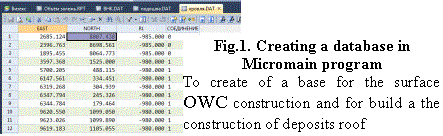
The
second stage – this is a database creation in Micromain program, which consists
on a new project creation and files attachment from the Microsoft Excel program. To do this, each file which you create
and save them in Microsoft Excel with the extension «.csv delimiters, commas»
allows you to use the data in Micromain. In Micromain program similar files are
created, in which all information is transferred (Fig. 1). The database is
checked for the errors absence. At the third stage with a help of creating
models pack consistently the roof was constructed, and in the same way creation
of a structural maps of the layer foot in isolines and surface. Then we
constructed the oil – water contact surface on the coordinates. Creating a
three-dimensional reservoir model included: separation all building surfaces –
the roof, sole and the surface of OWC; unification their into unified framework
model;
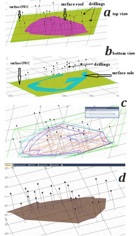
Fig.2. Creating three-dimensional model of oil deposits
The intersection of the OWC surface
with the deposits surfaces: a - with the roof, b - with the sole; c - the creation of wireframe model combines all three surfaces (roof,
sole, OWC); d - the creation of deposits three-dimensional model.
choice deposits space of its – by
cutting unnecessary parts of the roof and sole, which are below the OWC
surface. Thus, necessary space is limited for following definition of his
volume. And then reservoir building space is saved in a separated file. Defining
the scope of deposits is carried out by opening the deposit file and accounting
through a modelling tool kit – «Volumes». The received information about the deposits
volume is used then for the calculation of oil reserves in Excel.
Without
the use of 3D modeling in the calculation of reserves there is a need to define
much more parameters, such as reservoir area on the roof and on the sole, the
average area, effective power, and others. Finding of the area is carried out
on pallets or by breaking down into simple shapes and consistent finding of the
figures private areas and then the whole area. The effective power is defined
as the arithmetic average or the weighted average depending on the deposit
complexity and intervals size of productive horizon crossing by the boreholes.
The accuracy of such determinations is significantly lower than during 3D
modeling, and the calculation process takes more time [1]. The accuracy of such
determinations is significantly lower than during 3D modeling, and the
calculation process takes longer.
By
result of modeling we can make conclusion to the effect that conducting
inventory counting by model creating in comparison with other methods is:
ü quicker and less labor-intensive;
ü much more precise - in the definition of the deposits volume.
This
technique with the necessary improvement can be used in the morphology modeling
of the morphology, development systems and reserves calculation in the gravel
deposits. Especially in the case of extensive placers when creating a model with
using cross-sections can be very difficult and not always correct as a result
of the intersection or overlay planes sections.
References:
1. Oil
and gas geology / S.V. Galkin, G.V. Plyusnin. – Perm: Perm national research polytechnic
university publishing house, 2010. – 96
p.