Danylova L.,PhD, Lanyn
O.
National Technical
University of Ukraine «Kyiv Polytechnic Institute»,
Kyiv, Ukraine
calculation
of the lead hole diameter for the UNC and UNF machine screw
In industry
and construction, Self-Drilling Thread-Forming Screws are used. Self-cutting
screws drill their own tapping hole to close tolerances and from their mating
themselves. The specially formed and stamped drill point prevents any drifting
around the surface of the component allows rapid spot drilling. There’s no longer
any need to centre punch the drilling point. No drilling or thread-cutting
tools needed, no additional securing elements needed. Thanks to this properties
self-cutting screws can be worked quickly and cheaply. Savings up to 50% are
possible compared with conventional tapping screws. Their effectiveness is determined by eliminating the
need to pre-drill holes in joined parts or extrusion of the threads and
accurate basing of the screw in the hole under the thread formation.
In general,
tapping screws permit rapid insertion because nuts are not used and access is
required from only one side of the joint. Mating threads created by these
tapping screws fit the screw threads closely, and no clearance is needed. The
close fit usually keeps the screws tight even when subject to vibrations.
Tapping
screws are used in steel, aluminum, die-castings, cast iron, forgings,
plastics, reinforced plastics, and resin-impregnated plywood. This method
provides a high yield, higher quality of connection, increase of static and
fatigue durability of screw-threads in comparison to screw-threads that are
cut.
Self-drilling screws for the application fixing to
steel, intended for drilling and tapping into layered or unlayered steel shall
be type ASD, BSD or CSD. TYPE ASD and BSD screw have spaced threads and type
CSD screws have threads of UNC machine screw diameter-pitch combination with a
60 degree basic thread form. Lead hole for thread traditionally defined on the ground of maintaining the constancy of volume before and after
plastic deformation, the various clarifications and limitations that take into
account the conditions of friction as strength, size tolerances. All these
specification necessary to reduce the likelihood for overflow profile of the thread. In case of the threads of UNC and UNF
machine screw lead hole for thread defined not only the constancy volumes before and after deformation, but the conditions of
similarity thread profiles on the screw and in the hole. Spaced threads forming the thread in the hole of a
different profile, so you can not apply the conditions are similar. Spaced
threads form the thread in the hole of a different profile, so you can not
apply the conditions of analogy.
Since the condition for preserving the
constancy of volume before and after plastic deformation abideth in strength,
it is necessary to determine the geometric parameters of the established
profile, such as raising the height of the deformed material. This can be done
using a solution of the classical problem of the theory of plasticity the penetration of
a smooth rigid wedge into a semi-infinite mass of rigid/perfectlyplastic
material. Based on the Figure 1 calculated
value of the diameter of lead hole for thread d0= (d-2t)/2+Dt. It
depends on the outside diameter d of the screw and of
indentation, the value of which is easily
determined depending on the desired size of the profile
height or taken from the drawing-rigid plastic region.
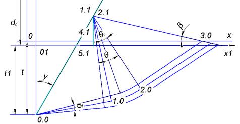
Figure.1. - The
scheme of the determination of the correction.
Method of
determining d0 is based on the classical problem of the theory of plasticity, such as solving the
problem of the penetration of a smooth rigid wedge into a semi-infinite mass of
rigid/perfectlyplastic material, to simulate any combination conditions of thread-formation (conditions of friction,
tightness, precision connection) for any combination s profile height and width
of the thread pitch.
This study
proposes an analytical model based on a study concerning radial penetration of
a rigid acute wedge into a perfectly plastic material. The method uses the
slip-line method with a model taking into account the interaction between two
consecutive formed threads and enables the mean pressure on the thread flank to
be obtained as a function of the formed thread height.
Figure 1 shows that
with increasing d
increased
free limits 2.1-3.0, which leads to the expansion of 2.1-3.0-2.0. This depth
introduction wedge t with
increasing d are reduced. According to the
theory Sokolovsky angles θ0 and β are independent of ![]() . The figure 4 depicts the variation of co-efficient of friction
with respect to semi wedge angle. With the increase of wedge angle the normal
force and tangential force increases. But, the variation of normal force is
very high. Again, it is clear that normal and tangential force increase with
increase of depth of indentation. But wedge surface pressure decreases with the
increasing wedge angle.
. The figure 4 depicts the variation of co-efficient of friction
with respect to semi wedge angle. With the increase of wedge angle the normal
force and tangential force increases. But, the variation of normal force is
very high. Again, it is clear that normal and tangential force increase with
increase of depth of indentation. But wedge surface pressure decreases with the
increasing wedge angle.
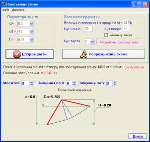
For calculating of lead hole for thread, propose program for visualization of the plastic
thread formed area. For specified parameters thread, friction coefficient and
filling thread profile is built right slip-line to
a particular case, taking into account the friction. The real picture of
deformation gives an opportunity to profile and overflow election under
diameter depending on requirements of threaded connection (Figure 2) .