*98823*
UDC
621.313.333.1
PROTECTION
SYSTEM OF SEMI-CONDUCTING RECTIFIER WITH APPLICATION OF MAGNETSENSITIVE
INSTRUMENTS
S.S.
Issenov, е-mail: isenov_sultan@mail.ru
Saken Seifullin
Agricultural University, Kazakhstan
At present about 1/3 of produced electric energy around the
world is transformed (with the help power electronics equipment) of before
utilization. Power electronics represents nowadays an electrotechnical sector.
Its output plays a vital role in electrotechnical and electric-power industries.
To prove that the following data are given below [1]:
1)
Annual usage volume around the world is (8…
12) *1012 K.W.H. Annual energy production expenses amount
400… 500$ billion. 72… 78$ billion amount real loss of generative,
transmitting and consuming objects;
2)
The main electric energy users are electric drives of various functions (51%),
lighting (19%), heating/cooling (16%), and telecommunication (14%);
3)
At present less than 25% of electric energy is used optimally to implement work
required (meaning loss minimization). This is achieved by application of
high-performance methods of electric energy network system’s controlled
transformation into energy of object control. The majority of such methods are
based on high-performance energy converters utilization.
The
progress in semiconductor electronics and transforming technique has influenced
greatly the electric-power industry development. Application of semiconductor
control systems and converters has made it possible not only improve some technical
and economic indexes of the systems exist, but also apply new principles of
control, the realization of which used to be unreasonable economically or
impossible technically. To supply different loads noncontrolled rectifier (NR)
is used in the number of direct-current and alternating-current drives. Strong
reliability demands are made of the system of noncontrolled rectifier – load.
That is why in order to protect the given system there are used quick-break
fuses and quick-operating catalyst and noncatalyst switching units and
protectors, which are installed at the point of entry and outlet of the
rectifier.
To
protect elements and optimize operating regime of noncontrolled rectifier -
load electrotechnical system improved in its characteristics (lack of contacts,
climatic impact resistance, and diminutiveness) a differential protection (DP)
is applied on basis of ferreed appliances. The high sensibility of
semiconductors’ electrical characteristics to different external actions
(magnetic field, temperature) makes it possible apply them as sensors that
measure and transform the corresponding impact magnitude.
Providing
overall protection is one of the solving ways in creation and perfection of
noncontrolled rectifier protection. The overall protection maintains the
rectifier elements and the whole system itself against possible emergency
state. A differential protection of
semi-conducting rectifier (SR) underlies the overall protection, taking into
account the most dangerous state that brings to overcurrent leaking.
There
is known the differential protection of NR [2]. One of its features includes
utilization of direct-current and alternating-current transformers as current
sensors. Here the direct-current transformer (DCT) is functioning as current
matching node at the NR indirect point of entry and outlet. This may be the
basis of the overall protection. However, it is necessary to perfect its
technical and economical indexes first: to exclude DCT, which doesn’t fully
meet the demands made to semi-conducting devices protection. It also requires
the break of output circuit of NR while examining, setup, or checking the DCT
and matching node. Moreover, while incrementing the noncontrolled rectifier –
load system the DCT mass and size indexes grow nonlinearly.
DP
is more economical when DCT functions are implemented by magnetic diode, which
is placed close to the NR output line or inside the resistor networked at the
outlet point of the NR. Application of high-speed protection system that forms
the basis of differential protection with direct-current and
alternating-current sensors is one of the solving ways of the problem set
(picture 1).
While
connecting semi-conducting rectifier according to the bridge circuit
VS1÷VS6 to ac network through the switching unit QF and a transformer
TV, a load is linked up at its outlet point. At the transformer point of entry
TA1÷TA3 alternating-current sensors are placed, to their entry point the
VS1÷VS6 noncontrolled rectifier is networked. NR goes out through the RU
nonlinear element, R1 resistor, VB1 controlling bundles of magnetic diode, KV1
sealed switch, trough the ILI gating circuit and is connected with the effector
(E). At the transformer outlet point a velocity sensor of current change is
placed on the basis of VD7÷VD9 magnetic diodes. The velocity sensor is
networked with the second entry point of the ILI element through the
single-limit comparator with feed back (VD10, VD11) and C1 condenser, which
compares the velocity sensor of voltage build-up with voltage reference Ureference. The ILI element outlet point is
networked through the effector (E) with the outlet point of nonautomatic
disengage unit and the controlling entry point of the commutation unit
disengagement. VB1 magnetic diode is placed close to the ac busbar. During the
normal operating conditions of SR there is a signal at the outlet point of the
nonautomatic engaging unit (NEU) that provides the starting of the commutation
unit. So the SR is connected with the ac network through TV transformer and to
the load by means of ac busbars. At the
same time rectified current proportionate to current at the SR entry point is
running along the VB1 magnetic diode gate winding and KV1 sealed switch. VB1
magnetic diode is in off condition as 2 magnetic fields are applied to it: one
from the gate winding and another one from SR ac busbar. The magnetic flow of
the VB1 magnetic diode’s gate winding is regulated by current change in the
winding with the help of R1 resistor. Magnetic field created by ac busbar is
regulated by the distance change between the busbar and the magnetic diode or
by the angle change between them. Under the action of the magnetic flow of KV1
sealed switch’s gate winding the latter flips (front contact seals in and back
contact breaks) thus effector (E) input circuit is prepared to act, and
signaling unit’s (SU) input circuit breaks.
|
|
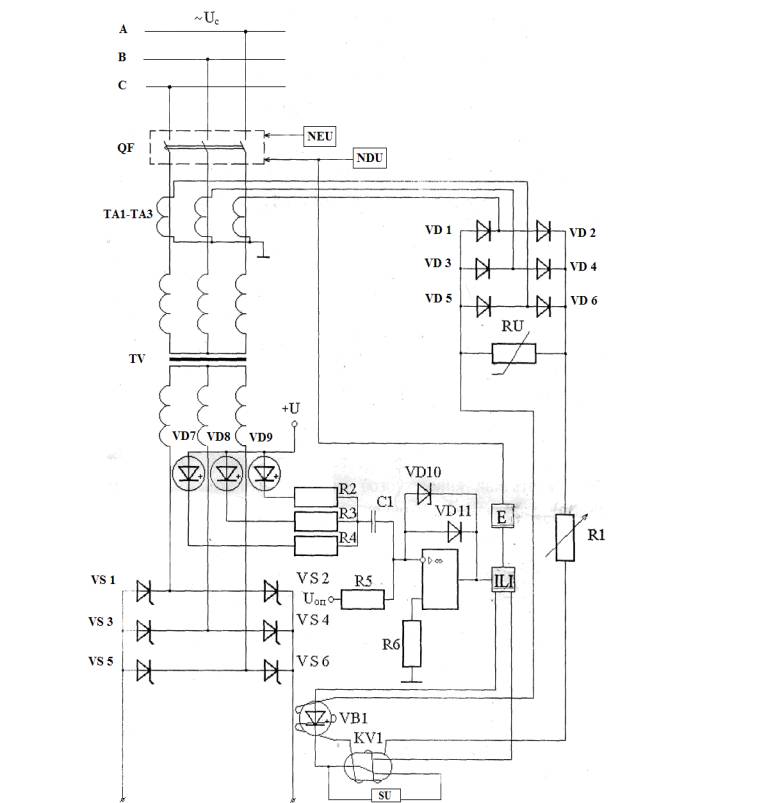
Picture
1 – Differential protection of the semi-conducting rectifier on magnetic diodes
The SU signalizes the
continuity of differential protection control circuit. There is no signal at
the first entry point of ILI element as VB1 magnetic diode is locked. There is
also no signal at the second entry point of ILI element because of the
comparator base, which does not act till the SR operates normally and current velocity
change di/dt at SR’s point of entry and consequently at the outlet point of the
current change velocity sensor is correspondent to the normal operating
condition of SR (di/dt<di/dtsteady). That is why there is no
signal at the entry point of ILI element and SR, and the commutation unit
remains engaged.
When
short circuit takes place in SR, at its entry and outlet points between the ac
busbars and in the load short-circuit current appears in the circuit between
the network and the short circuit point. At the same time short-circuit current
velocity exceeds greatly current velocity change controlled by the velocity
sensor of current change in the ac circuit at SR. That is why the signal at the
outlet point of the velocity sensor of current change is strong enough to make
the comparator base act (di/dt>di/dtsteady) and at the outlet
point of the latter a signal appears, which comes in the second entry point of
the ILI element.
At
the outlet point of ILI element a signal appears that comes in the entry point
of the effector (E). The effector (E) acts and gives signal to the commutation
unit’s controlling entrance. The latter acts and disengages the SR power
circuit from the ac network.
DP
also acts at overcurrent. Current increases proportionally at the SR points of
entry and outlet. However, magnetic fluxes influencing the VB1 magnetic diode
increase proportionally to the current of protection act, when the RU nonlinear
element goes into action. Then the RU nonlinear element limits the voltage at
the NR outlet point and therefore limits the current and magnetic flux of the
VB1 magnetic diode’s gate winding, it opens; at the first entry point of the
ILI element a signal appears and at the outlet point of the latter a signal
appears also. This signal sets the effector (E) going, and the commutation unit
disengages the SR from the ac network.
To
disengage the SR a signal is made by the nonautomatic disengaging unit (NDU).
The signal goes to the controlling entry point of the commutation unit
disengagement, which disengages the SR from the ac network.
Conclusion:
application of DP of semi-conducting rectifier helps cut maintenance charges.
There are several advantages of the DP application: the opportunity of full
interconnection of entry and outlet circuits, non-contact transformation of
little mechanical motions into electrical signals, magnitude detection and
direction of magnetic field induction with high locality, the “non-sparking”
mechanical commutator creation in circuits, and non-contact current test.
Literature
1. G.S.Zinoviev.
Theory of power electronics. Tutorial. 3rd edition revised and
augmented. – Novosibirsk. Publication of NSTU (Novosibirsk State Technical
University).2004.-672 p.
2. V.S.Kopyrin,
V.P.Markowskiy. Differential protection of the non-controlled rectifier – drive
winding system//Science and new technology in power industry of
Pavlodar-Ekibastuz region: thesis report. – Almaty, 1994. 68-71 p.