Kovalenko M.A., Ph.D. in
Technical Sciences., assistant; Pelypenko K.O., student.
National Technical University of Ukraine «Kyiv
Polytechnic Institute»
The development of three-dimensional math model of inductive diagnosis
system for induction motors with centrifugal production method
Introduction. Nowadays
Electrical Repair services are applying «visual» diagnosis of rotor damages in
the process of the Induction Motor (IM) repairing. Usually this process
contains rotor overview and without visible damages being identified one
continues to use the rotor as a component of renovated IM. However, such
practice does not meet the modern requirements for providing reliable work of
repaired electrical equipment because of the frequent cases of motor breakdown
after short-term use; it can be related with the damaged stator winding, caused
by work with faulty squirrel cage (or short-circuited rotor winding).
With the centrifugal method of rotor
production, rod resistance has anisotropic properties and during inductive
diagnosis, rotor inaccuracies may be encountered.
Aim of work. The purpose is the development of math model of system, which is called
«The IM rotor as an inductive device», and the research of diagnostic features
with the use of centrifugal and static methods of a squirrel cage production.
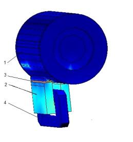
Materials and research results. In
this work a three-dimensional math model of inductive devise has been
developed, as it is shown on the figure 1 (a): 1 – rotor under investigation, 2
– magnetic core of inductor, 3 – measurement winding (MW), 4 – excitation
winding (EW). The model is numerically implemented in COMSOL Multiphysics 4.4
pack.
The damage of squirrel cage rods is
represented with conductivity decrease in rod material, in extreme case it`s
conductivity is equal to zero during the collapse of rod.
The EMF of measurement winding is
calculated by the value, attached to a resulting magnetic flux of MW:
![]() (1)
(1)
Where Bn – normal component of magnetic
induction at MW surface area, WMW – number of turns on MW, SMW – surface area
with MW placed in;
In the case of spinning anisotropic
properties of rods material in the investigated rotor are simulated as follows:
 (2)
(2)
where
![]() – aluminium electrical conductivity; x, y
– Cartesian coordinates.
– aluminium electrical conductivity; x, y
– Cartesian coordinates.
Inner cracks in the rod of squirrel-cage
rotor and inner cavernes were analysed.
Figure
1 (b) shows the distribution of conductivity throughout the height of slot with
the use of spinning in the motor 4A112M4Y3.
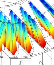
a)
b)
Fig. 1 – calculated system area
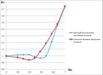
Figure
2 is the dependency graphs of crack hights 2 (a) and cavern areas 2 (b) and
their dependence on multiple Ke for both static and centrifugal methods.
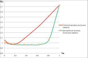
a) b)
Fig.
2
Conclusion: designed
math model should be used for methodological support for fault detection
systems. They may find defects of squirrel cage rotors in IM with different methods of priming.
References
1.
Vaskovski
U. M. Field analysis of electric machines: Teaching Manual – K.: NTUU «KPI»,
2007 – 192 c.
2.
Taran
V. P. Diagnostical electric equipment – K.: Machinery, 1983. – 200 c.