Mel’nick V.N.
National Technical
University of Ukraine “KPI”
INFLUENCE OF ULTRASONIC WAVES ON THE GYRO’S GIMBAL
We will
take into consideration eight values of the turning angle of the ДУСУ body relative about its longitudinal axis, i.e.
every ![]() starting with
conditional zero (denoted by
starting with
conditional zero (denoted by![]() ). When the gyromotor power is off we mark "zero shift" on the diagrams of the
output signal of the angle rate sensor by a thin line. A thick line marks the
output signal when the gyromotor power is on (Fig. 1, Fig. 2). The first five -
seven seconds and last five- seven seconds of implementations can be excluded
because it is time for a nominal mode of the gyro radiator and a stoptime, respectively.
The device and the radiator operate in a non-stationary mode.
). When the gyromotor power is off we mark "zero shift" on the diagrams of the
output signal of the angle rate sensor by a thin line. A thick line marks the
output signal when the gyromotor power is on (Fig. 1, Fig. 2). The first five -
seven seconds and last five- seven seconds of implementations can be excluded
because it is time for a nominal mode of the gyro radiator and a stoptime, respectively.
The device and the radiator operate in a non-stationary mode.
The gyrodevice is “off”. As it can be seen, the output signal of the angle
rate sensor in the ultrasound beam undergoes stochastic changes at the
value and the sign. The value of "zero shift" can grow to ![]() (in terms of angle
rate). At the
(in terms of angle
rate). At the ![]() "zero shift" is practically missed,
more exactly, it is below the sensitive threshold of the sensor.
"zero shift" is practically missed,
more exactly, it is below the sensitive threshold of the sensor.
Minor
changes in sign in the output signal occur in ![]() (Fig. 1). Instead, when
(Fig. 1). Instead, when ![]() , they do not only range in sign, but have a substantial
range in the amplitude. If the angle
, they do not only range in sign, but have a substantial
range in the amplitude. If the angle ![]() , the range of values is greater than
, the range of values is greater than ![]() , but always an unchanged sign.
, but always an unchanged sign.
Obviously,
the existing "zero shift"
in the ultrasonic ДУСУ sensor rays when the gyromotor is off is determined the
integral reaction of the gyroscope gimbal components. First of all, it concerns the current-collectors of the
potentiometer, which look like a console.
Not the
least part play the nonlinear oscillations of the "float" surface as well as emerging caustic areas which are
results of resonance phenomena of wave coincidence.
 The gyrodevice is “on”. Of course, under
these conditions serious changes of the output signal of the device will take
place due to a gyroscopic reaction. If
The gyrodevice is “on”. Of course, under
these conditions serious changes of the output signal of the device will take
place due to a gyroscopic reaction. If ![]() , the device error
, the device error ![]() is being increased
almost in ten times and changes its sign (Fig. 1). The maximum value of it
reaches
is being increased
almost in ten times and changes its sign (Fig. 1). The maximum value of it
reaches![]() . The average value equals
. The average value equals ![]() .
.
Fig. 1.
The ДУСУ output signal at ![]() ;a thin line – the gyrodevice is “off” ; a thick line – the gyrodevice is “on”
;a thin line – the gyrodevice is “off” ; a thick line – the gyrodevice is “on”
If ![]() , the average error
, the average error ![]() and its maximum value
and its maximum value
![]() is slightly decreased
in magnitude, but changes its sign for the opposite (Fig. 2):
is slightly decreased
in magnitude, but changes its sign for the opposite (Fig. 2):
![]() ,
, ![]() .
.
A turn
of the ДУСУ body at the angle ![]() allows stabilize the
error of the device in time at the level
allows stabilize the
error of the device in time at the level ![]() .
.
A turn
of the ДУСУ body at the angle ![]() allows reduce the
average error to the value.
allows reduce the
average error to the value. ![]() . However, the range of values will be. In addition a
superposition of short-period and long-period components take place.
. However, the range of values will be. In addition a
superposition of short-period and long-period components take place.
If the
angle ![]() , the ДУСУ output signal has a minimal variation in
amplitude, and the average error does not exceed
, the ДУСУ output signal has a minimal variation in
amplitude, and the average error does not exceed ![]() .
.
A turn
of the ДУСУ body at the angle ![]() practically does not
change the situation. The same concerns the numerical values.
practically does not
change the situation. The same concerns the numerical values.
At the
turning angles ![]() and
and ![]() the diagram of the error
is not changed. The average value also won’t be changed.
the diagram of the error
is not changed. The average value also won’t be changed.
![]()
and
remains stable over time. At the same time a slight range appears. Thus, the
angular orientation of the ДУСУ body at values ![]() ,
,![]() ,
, ![]() and
and![]() practically have no effect on the diagram of the device’s
error over time.
practically have no effect on the diagram of the device’s
error over time.
![]()
t, s
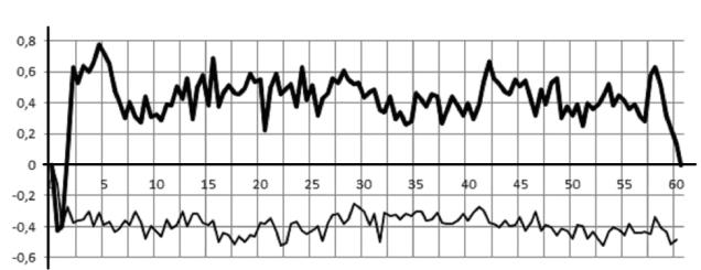
Fig. 2.
The ДУСУ output signal at ![]() : a thin line – the gyrodevice is “off”; a thick line – the gyrodevice is “on”
: a thin line – the gyrodevice is “off”; a thick line – the gyrodevice is “on”